Parts list, General information – Wilwood Forged Dynalite Pro Series Front Brake Kit User Manual
Page 3
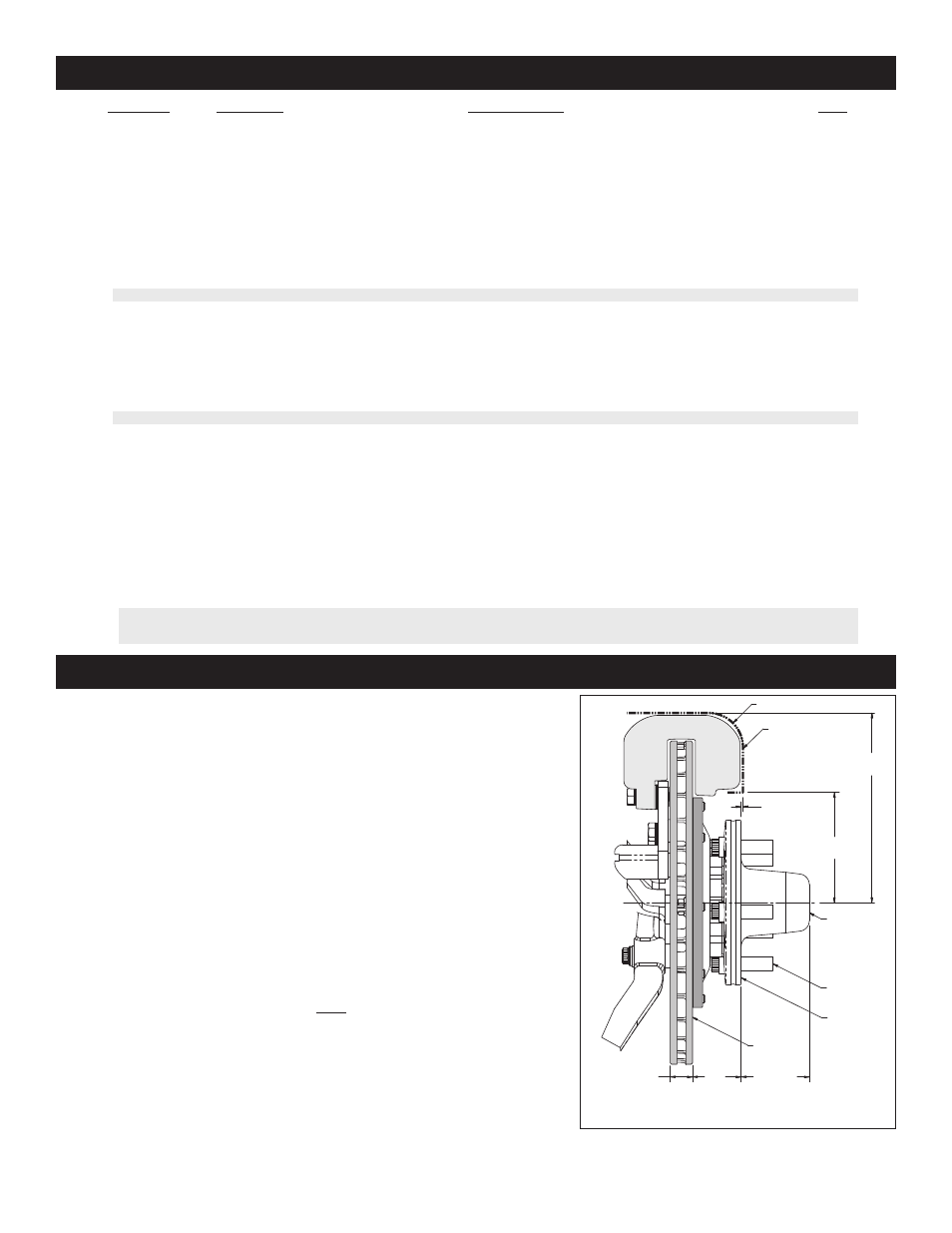
Parts List
1
2
3
4
5
6
7
8
9
10
11
11A
12
13
14
15
16
17
18
18A
19
20
21
22
23
24
1
4
8
4
2
10
2
2
2
2
2
2
16
10
2
2
2
2
2
2
16
4
4
1
2
2
249-11035/36
230-10426
240-11101
230-9182
230-10421
230-2187
270-11032
370-0879
380-0928
300-3099
160-5841
160-7101/02-BK
230-11934
230-11239
370-0877
240-2283
211-1674
270-2158
120-6816
120-6816-RD
240-1159
240-10190
230-10025
150-8850K
180-0055S
300-11961
ITEM NO.
PART NO.
DESCRIPTION
QTY
NOTES: Part Number 230-11052 Bolt Kit, bracket bolt kit, includes part numbers 230-9182, 230-10421, 230-10426 and 240-11101
Part Number 230-3829 Bolt Kit, adapter plate to hub, includes part number 230-11239
Part Number 230-12120 Bolt Kit, rotor to adapter plate, includes part number 230-11934
Part Number 230-11861 Bolt Kit, caliper to bracket, includes part numbers 230-10025, 240-10190 and 240-1159
Item 11A is an optional item and is available in the (D) drilled rotor kits. Add -D to end of part number when ordering.
Item 18A is an optiona litem and is available in the (R( red caliper kits. Add -R to end of part number when ordering.
General Information
Page 3
- Aluminum Tandem M_C Kit with Bracket and Valve (1 page)
- W4A Big Brake Rear Parking Brake Kit (9 pages)
- Brake & Clutch Pedal Description (3 pages)
- Brake & Clutch Pedal Description (4 pages)
- Brake & Clutch Pedal Description (5 pages)
- W6A Big Brake Front Brake Kit (Race) (7 pages)
- GP320 Sprint Left Front Brake Kit (6 pages)
- MasterCylinder No: 260-3501 (2 pages)
- Stealth Motorcycle Front Brake Kit (4 pages)
- Billet Superlite 6 Lug Mount Caliper (4 pages)
- MasterCylinder No: 260-9921 (1 page)
- Dynapro Dust-Boot Rear Parking Brake Kit (10 pages)
- W4A Big Brake Rear Brake Kit For OE Parking Brake (8 pages)
- SC1 Single Piston (1 page)
- Forged Narrow Superlite 4R Big Brake Rear Brake Kit For OE Parking Brake (8 pages)
- Dynapro Radial Front Drag Brake Kit (7 pages)
- Dynapro 6 Big Brake Front Brake Kit (Hub) (8 pages)
- Promatrix Front Replacement Rotor Kit (6 pages)
- D8-6 Front Replacement Caliper Kit (6 pages)
- Compact Remote Flange Mount Master Cylinder (6 pages)
- W4A Big Brake Front Brake Kit (Race) (7 pages)
- Forged Dynalite Front Drag Brake Kit (Hat) (8 pages)
- W4A Big Brake Truck Rear Brake Kit (7 pages)
- Dynapro Radial Big Brake Front Brake Kit (Hat) (7 pages)
- Narrow Dynapro Radial Mount (2 pages)
- Dynapro Dust-Boot Pro Series Front Brake Kit (9 pages)
- GM III Single Piston Floater (2 pages)
- Billet Superlite 4R Radial Mount (2 pages)
- Dynapro Dust-Boot Big Brake Front Brake Kit (Hub) (9 pages)
- High Volume Master Cylinder (2 pages)
- D52 Rear Caliper Kits (5 pages)
- Forged Narrow Superlite 6R Big Brake Front Brake Kit (Hat) (7 pages)
- Promatrix Front and Rear Replacement Rotor Kit (5 pages)
- Dynapro Single Front Drag Brake Kit (8 pages)
- Powerlite Radial Mount (2 pages)
- HI-TEMP Brake Fluid (1 page)
- Dynapro SA Lug Drive Dynamic Rear Drag Brake Kit (9 pages)
- MC4 Mechanical (1 page)
- W4A (2 pages)
- EXP600 PLUS Brake Fluid (1 page)
- D154 Front Caliper Kits (6 pages)
- 60 Degree Pedal Description (6 pages)
- Forged Dynalite Pro Series Rear Brake Kit (8 pages)
- Dynapro Dust-Boot (2 pages)