Pre-measuring for alignment – Grain Systems Bucket Elevtors, Conveyors, Series II Sweeps PNEG-1412 User Manual
Page 14
14
PNEG-1412 Two Leg Towers
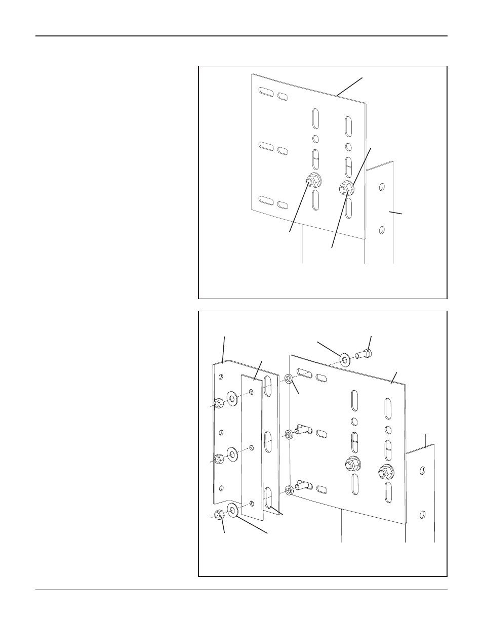
Figure 2
This step is to locate the placement
of the bin bracket. All bin bracket
bolts must line up on the “hill” of the
corrugation. If this “pre-measuring” is
done correctly, no adjustments
should be needed to align holes on
hills after the tower is lifted into
place.
ATTACHING LATERAL
BRACKET, BIN BRACKET, &
BACKING PLATE TO COLUMNS.
1. Align holes & attach lateral brack-
ets (STC00355) to top of bottom
columns using (2) 1/2" x 1" bolts, (2)
1/2" flat washers, & (2) 1/2" hex nuts
for each column. NOTE: Bolt heads
go to inside of column. Do not
fully tighten bolts. (See Figure 2.)
2. Attach bin brackets (STF00016)
and backing plates (STF00021) to
lateral brackets using (3) 3/8" x 1"
HHCS bolts, (3) spacers, (6) wash-
ers, and (3) hex nuts as shown in
Figure 3 for each column. NOTE:
Bolts should be placed in the
bottom half of the bin bracket
slots. Fasten only finger tight to
allow bin to settle.
Pre-Measuring for Alignment
Figure 3
Lateral Bracket
(STC00355)
1/2" x 1" HHCS Bolt
(S-4492)
1/2" Hex Nut
(S-3729)
1/2" Flat Washer
(S-2120)
Column
Lateral Bracket
(STC00355)
3/8" Flat Washer
(S-248)
3/8" Hex Nut
(S-456)
3/8" x 1" HHCS Bolt
(S-8671)
Column
3/8" Spacer
(STF00022)
3/8" Flat Washer
(S-248)
Bin Bracket
(STF00016)
Backing Plate
(STF00021)
NOTE: These bolts are to be finger tight only and
should be placed in the bottom half of the slot.
Bin Bracket SLOTS