Fan placement – Grain Systems Bin Flooring PNEG-1324 User Manual
Page 16
3. Installation
16
PNEG-1324 72', 75', 78', 90' and 105' Cor-Lok and Cut-Lok Flooring
Fan Placement
Fans should be placed to provide the most uniform airflow and to minimize blockage of air flow by floor
supports and unloading equipment. Consult with GSI for advice on specific cases.
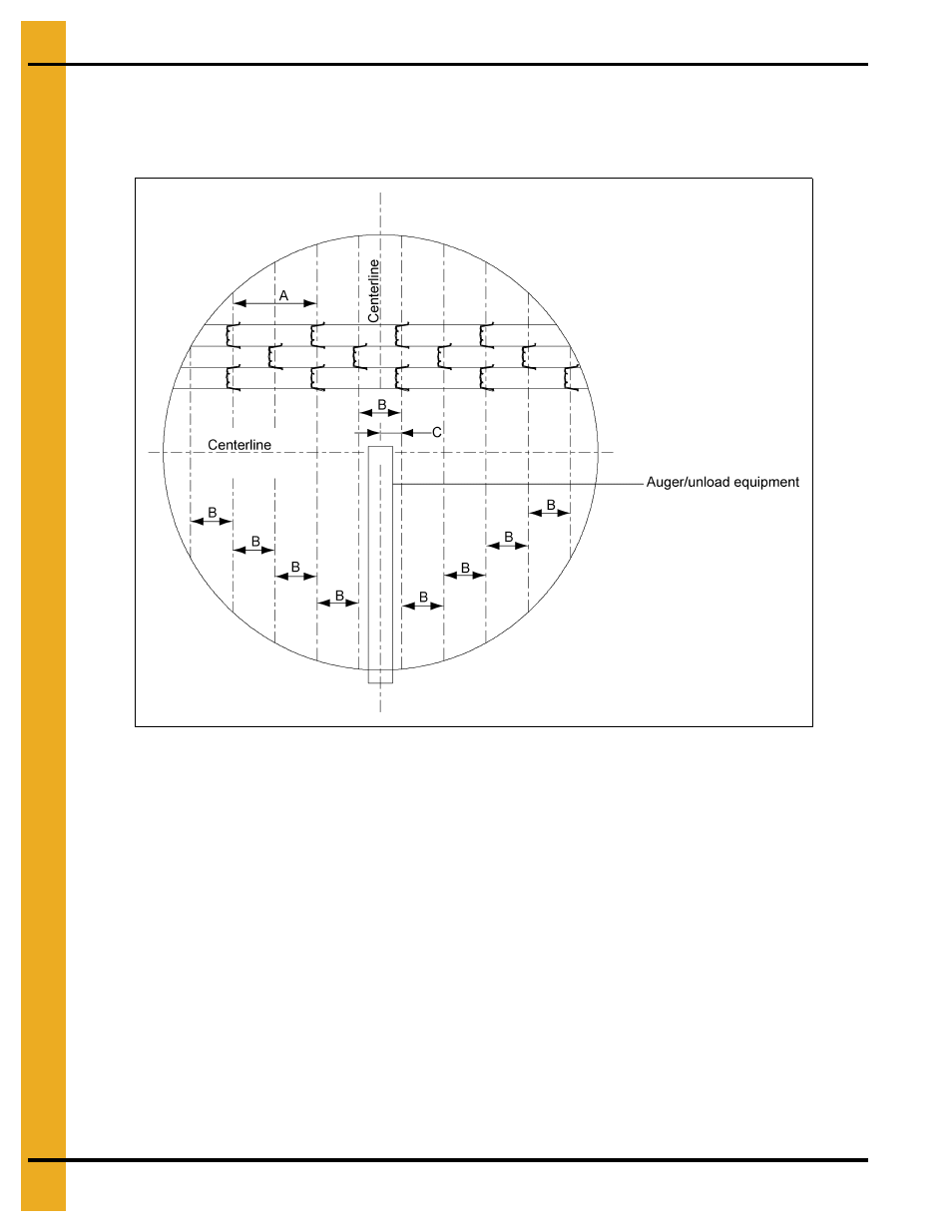
Figure 3A
Grain Systems Recommended Method for Full Floor Installation
This method should save floor construction time and eliminate problems of improper installation which
could invalidate warranty. Dimension “A” is the leg-to-leg spacing along the centerline of a given plank.
Dimension “B” is the amount of stagger between supports under adjacent planks and is half of “A”.
Dimension “C” is the distance from the center of unload auger to the nearest rows of supports and
is half of “B”. See
on maintaining spacing requirements over unload equipment.
Grandstand quantity as well as dimensions “A” and “B” are provided in the support spacing and quantity
chart
1. Layout centerlines of tank being sure one centerline is in line with the direction of the flooring planks
while the other centerline is perpendicular with the flooring planks.
2. Measure over “C” dimension from centerline that is perpendicular to the direction of the flooring
planks. Do this at each end of the bin. Strike a chalk line here.
3. Measure over “B” dimension from the previously chalked line in
Continue this procedures until the bin wall is reached in both directions.
4. When completed there should be a set of parallel lines “B” dimensions apart.