Banks Power 2001-2004 (LB7) Chevy_GMC 6.6L Duramax Turbo-Diesel Pickups User Manual
Page 9
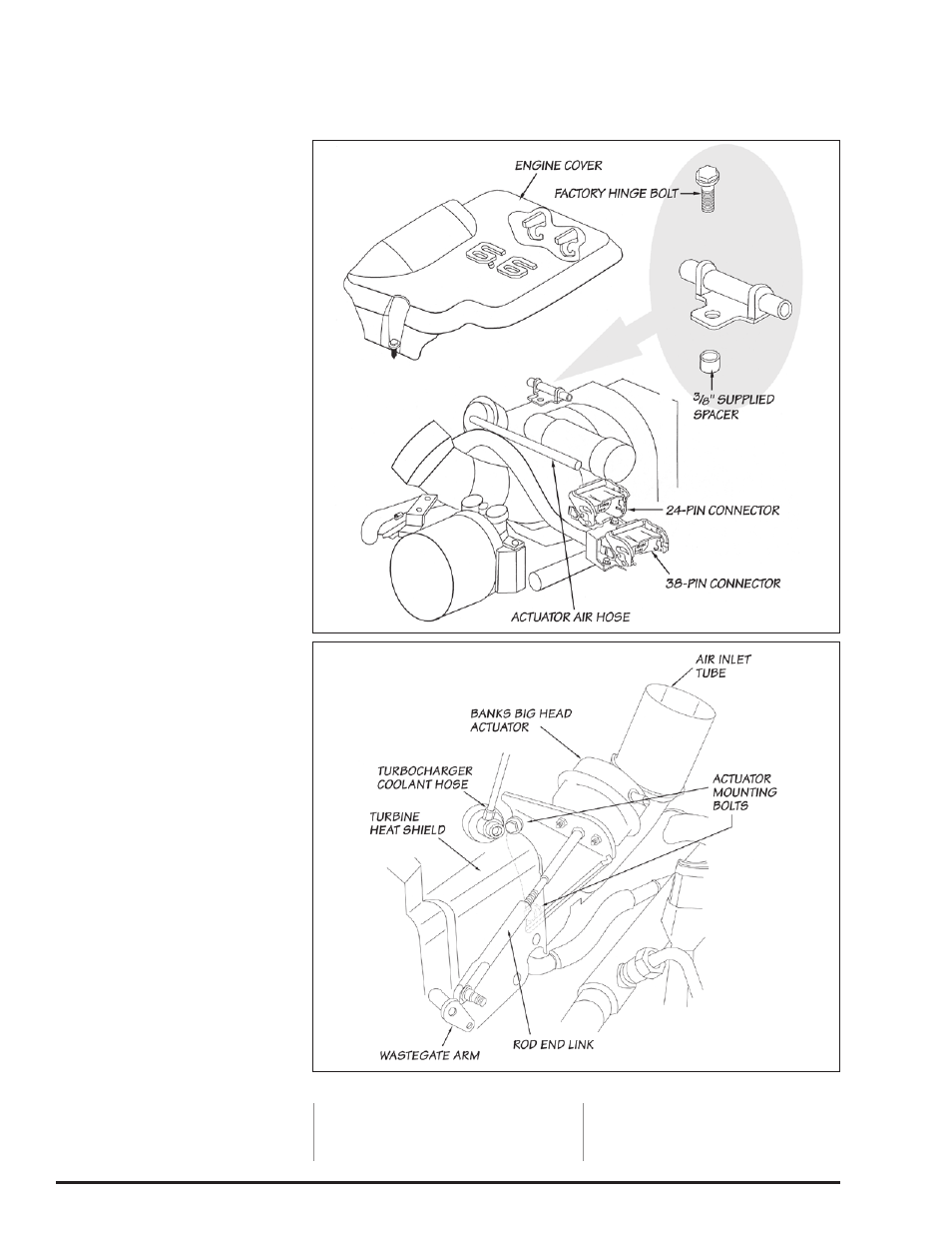
32.
Allow the engine to cool so that
coolant pressure is minimal. Remove
the plastic engine cover from the top
of the engine (see Figure 5). Remove
the three (3) mounting bolts of the
turbine heatshield to allow access to
the actuator bracket bolts.
33.
Remove the E-clip from the pin
through the wastegate arm. Remove
the top turbocharger coolant inlet
hose with a #55 torx wrench (see
Figure 6). Be sure to retain gaskets
and torx bolt for installation.
34.
Remove the actuator air hose
at the compressor outlet. Pressurize
the inlet air hose with a regulated
supply of air pressure to relieve
tension on the actuator pin. Remove
the pin from wastegate arm. Remove
the two actuator bracket bolts from
the compressor housing with a 12-mm
socket and retain for installation.
35.
Remove the factory actuator,
mounting bracket and air hose from
engine.
36.
Hold the Banks actuator bracket
up against the compressor housing in
the factory location. Turn the rod end
link on the threaded shaft until the pin
can be inserted into the wastegate
arm with the wastegate in the closed
position and the actuator bracket flush
against the back of the compressor
housing. Remove the pin and turn the
rod end link five (5) turns in to shorten
the rod.
WARNING: Be certain the end
link is adjusted correctly. If the
end link is adjusted more than
five (5) turns, overspeeding of the
turbocharger can result.
37.
Insert the rod end link pin into
the wastegate arm. Install the locknut
and
1
⁄
4
” AN washer onto the pin and
tighten to 25 in-lb (not ft-lb). Be careful
not to over tighten and damage the
pin.
38.
Install the lower actuator bracket
mounting bolt and engage the first
three (3) threads.
39.
Install the supplied
1
⁄
4
” air hose
onto the Banks Big Head actuator.
Secure with the supplied
7
⁄
16
” spring
band clamp. Apply 50-60 PSI of air
pressure to the actuator inlet hose.
40.
Install the second mounting bolt
and tighten both bolts. Be careful not
to over tighten.
41.
Install the
1
⁄
4
”air hose onto the
compressor outlet fitting. Secure with
the supplied
7
⁄
16
” spring band clamp.
42.
2001 vehicles only: Remove
the rear hinge for the engine cover.
Install the supplied
3
⁄
8
” spacer under
the hinge and re-install the hinge
bolt. Re-install the engine cover (see
Figure 5).
-END, SEcTION 3-
Section 3
ACTuAToR INSTALLATIoN
Figure 5
Figure 6
96773 v.7.0
9