Banks Power 2001-2004 (LB7) Chevy_GMC 6.6L Duramax Turbo-Diesel Pickups User Manual
Page 11
harness onto the male 38-pin
connector of the factory harness.
Repeat this process with the 24-pin
connectors.
47.
Attach the thermocouple to
the supplied thermocouple leadwire
extension with supplied nuts and
bolts. cover this joint with the supplied
heat shrink tubing and heat until the
tubing conforms to the joint. Make
sure the entire joint is insulated. Route
the thermocouple leadwire along the
factory harness to the driver’s side
and through the rubber grommet in
the firewall to the OttoMind.
For vehicles with manual
transmissions proceed to Step 50.
The TCC harness will not be used.
48.
Locate the Transmission control
Module (TcM) mounted on the left
side of the radiator fan shroud behind
a black plastic housing. Remove
the two (2) 6mm bolts holding the
plastic TcM housing to the radiator
and remove the housing. Attach a
red T-tap to the BROWN wire on
pin 29 of the top connector. Attach
another red T-Tap to the GREEN wire
with a WHITE stripe on pin 32 of the
top connector. The GREY connector
wire cover is split in the middle and
can be separated with a small screw
driver to allow access to the back of
the connector so the pin numbers
are viewable.
49.
Install the male spade connector
on the end of the GREY wire of the
supplied Torque converter clutch
(Tcc) harness to the red T-Tap
installed on the BROWN wire in
Step 48. Attach the BLUE wire of
the Tcc harness to the red T-Tap on
the GREEN wire with WHITE tracer.
Route the Tcc harness through
the grommet on the firewall to the
OttoMind. Re-install the TcM housing
onto the radiator fan shroud. Make
sure the tabs on the bottom of the
housing are inserted into the slots on
the tab of the shroud.
50.
From inside the cab, with the
lower dash panel removed, route the
main 10-pin and 8-pin connectors,
Tcc harness and thermocouple
leadwire on the left side of the
support bracket. connect the
coupled 10-pin and 8-pin connectors
and thermocouple leadwire into the
corresponding OttoMind connections.
connect the single 8-pin connector
into the bottom of the OttoMind. For
automatic transmission only, connect
the 4-pin male connector of the Tcc
harness (if applicable) into the 4-pin
female connector on the OttoMind.
51.
Insert the OttoMind on the
outside of the left steering column
support bracket between the left dash
panel. Orient the OttoMind such that
the 8-and 10-pin receivers are upright.
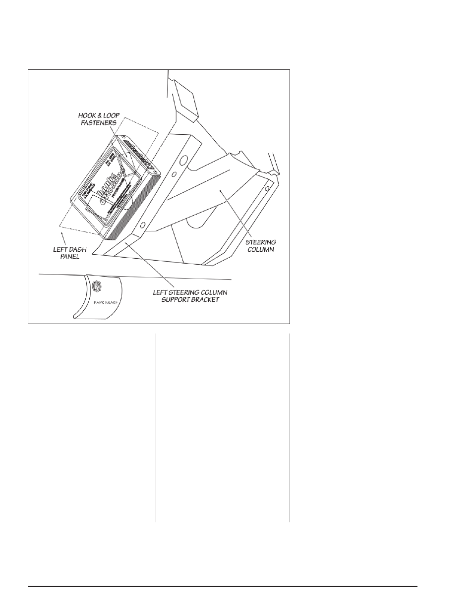
52.
The OttoMind is to be installed
on the outside of the left steering
column support bracket (see Figure
9). Make sure the outside of the
column support bracket is free of oil,
grease and dirt.
53.
With the OttoMind positioned
under the dash, just outside the left
steering column support bracket,
peel the protective backing from
the hook and loop interlocking
fastener attached to the OttoMind.
The OttoMind should be oriented
such that the pair of 8-pin and 10-
pin connectors are upright and the
Tcc connector and single 8-pin
connector are facing downward. With
the OttoMind’s long outside edge
parallel to the support bracket, press
the adhesive onto the outside of
the support bracket (see Figure 9).
Apply light pressure to the OttoMind
by hand for 60-seconds to create a
strong bond between the bracket and
hook & loop interlocking fastener.
Using the supplied cable ties, secure
the wire harness under the dash
away from any pedals or moving
components.
-END, SEcTION 4-
Figure 9
96773 v.7.0
11