Banks Power 2001-2004 (LB7) Chevy_GMC 6.6L Duramax Turbo-Diesel Pickups User Manual
Page 6
1.
As a precaution, disconnect the
ground of the battery (if there is
more than one battery, disconnect
both).
2.
Raise the vehicle and support it
with properly weight rated safety
stands, ramps or a commercial hoist.
Follow the manufacturer’s safety
precautions. Take care to balance
the vehicle to prevent it from slipping
or falling. When using ramps, be
sure the front wheels are centered
squarely on the topsides; place the
transmission in park; set the parking
brake and place blocks behind the
rear wheels.
CAuTIoN: Do NoT WoRK uNDeR
ANY VeHICLe SuPPoRTeD oNLY
BY A JACK. SeVeRe INJuRY MAY
ReSuLT.
3.
Removal of the factory exhaust
can be simplified by cutting the
factory exhaust pipe behind the
muffler. This will allow the tailpipe to
be removed as a separate piece.
4.
Remove the four (4) nuts from the
factory exhaust flange located at the
back side of the factory head pipe
(retain for re-use).
5.
Remove the factory tailpipe
from the vehicle by disengaging the
exhaust system hanger pins from the
rubber hangers using a large screw-
driver or pry bar. Note: Lubricating
the rubber hangers with WD-40 or
similar lubricant will ease removal of
the hanger pins.
6.
Remove the factory muffler from
the vehicle by disengaging the hanger
pins from the rubber hangers using a
large screwdriver or pry bar.
NOTE: If system 48682, 48683 or
48684 is being installed, perform
steps 7 thru 10 below. Otherwise
continue installation with step 11.
7.
Spray penetrating oil such as
WD-40 on the T-bolt of the factory
v-band clamp to prevent galling.
Remove factory v-band clamp and
save for re-use.
8.
Remove factory head pipe from
the vehicle by disengaging the
exhaust system hanger pins from
the rubber hangers using a large
screwdriver or pry bar.
9.
Install Banks head pipe in vehicle
and insert the hanger pin in the
rubber exhaust hanger.
NOTE: Be sure to install the hanger
pin in the same location as the
previously removed factory head
pipe.
10.
Loosely install v-band clamp on
head pipe flange and only tighten
the T-bolt on the clamp to the point
that the pipe is snug but can still be
rotated in the clamp for adjustment/
alignment. NOTE: Do not completely
tighten the V-band clamp at this
point.
CAuTIoN: The following step
involves cutting a stainless steel
tube. Safety glasses should be
worn during any cutting operation
and care should be taken to avoid
injury due to sharp edges and
burrs.
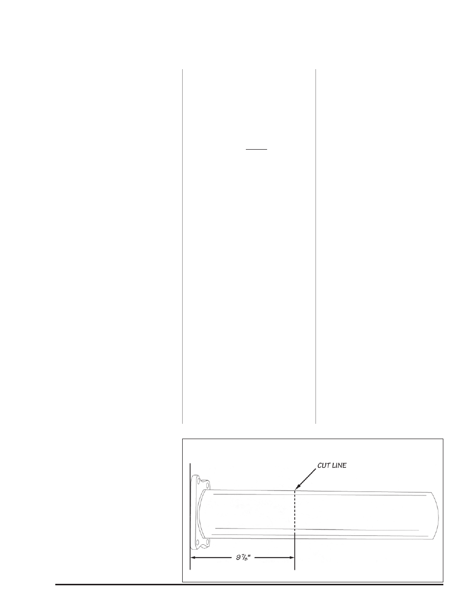
11.
If the system is being installed
on an extended-cab long-bed or an
extended-cab short-bed vehicle, the
flange pipe that is supplied must be
trimmed to the appropriate length
prior to installation in the vehicle.
Once the cut has been performed,
debur the cut end with a file or
sandpaper. Figure 1 illustrates
the location of the required cut,
depending on vehicle configuration.
12.
Slide the supplied 4-inch band
clamp over the Banks flange pipe.
13.
Insert the flange pipe tube end
into the slip joint on the intermediate
pipe.
NOTE: Once the pipe has been
completely engaged in the slip joint,
it should be marked with a marker,
scribe or tape for reference when
tightening clamps later in the
installation. Each slip joint in the
system should be marked in this
fashion. When the exhaust system is
being adjusted to align the hangers,
the slip joints can be adjusted so that
the reference mark is no more than
1
⁄
4
” away from its original position.
14.
Install the intermediate pipe/flange
pipe to the 4-bolt flange using the
factory nuts (see note below). Install
the supplied gasket between the two
flanges. Torque nuts to 30 ft-lbs. NOTE:
If system 48682, 48683 or 48684 is
being installed, use supplied
7
⁄
16
nuts,
bolts and washers on 4-bolt flange and
torque to 40 ft-lbs.
15.
Slide one (1) of the supplied
4-inch exhaust clamps over the
Banks intermediate pipe. Note: On
extended-cab long-bed and crew-cab
long-bed vehicles, the clamp that is
used between the intermediate pipe
and muffler is a combination hanger/
clamp. When this hanger clamp is
installed the hanger pin should be
inserted into the factory rubber
hanger and the clamp should be
rotated until the hanger pin is parallel
with the frame mounted pin before
being torqued.
16.
Install the muffler onto the end
of the intermediate pipe. Be sure that
the inlet side of the muffler (see
markings on muffler body) is facing
toward the front of the vehicle. verify
that the muffler and intermediate
pipe are completely engaged.
17.
Slide one (1) of the supplied
4” exhaust clamps over the Banks
Dynaflow muffler outlet.
18.
Install the tailpipe into the outlet
of the muffler. Be sure that the two
pipes are completely engaged. Insert
the front and rear hanger pins into
the factory rubber hangers. Rotate
the tailpipe until the hanger pins are
parallel with the frame mounted pin.
NOTE: Minimum distance between
Section 1
exHAuST ReMoVAL
Figure 1
6
96773 v.7.0