Banks Power Cummins Motorhomes: (Diesel ’98 - 03 ISB 5.9L) PowerPack TLC & Stinger TLC systems w_OttoMind Module 5.9L, Class-A MHExcept Comon Rail User Manual
Page 5
provided.
For Stinger installation, proceed to Step 26.
HIGH-RAM INSTALLATION
Disconnect the hose joint at the inlet end of
the factory intake casting. Remove the four
bolts that mount the inlet casting to the intake
manifold and remove the factory casting.
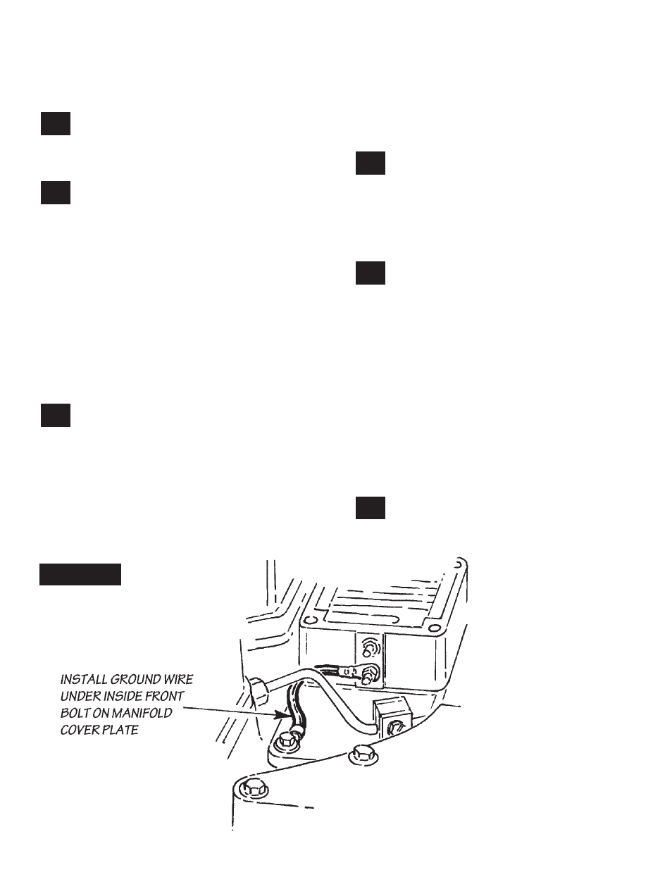
Remove the front inboard bolt from the
base plate of the intake manifold. Loosen
the nut on the ground strap for the intake heater
element and rotate the cable around so that the
ring terminal can be reinstalled under the head
of the intake bolt. Important: do not allow the
terminal on the element end of the ground cable
to come in contact with the upper heater lug or
with the injector line. Retighten the retaining nut
and reinstall the front intake manifold bolt through
the ring terminal. (See
Figure 3.
) NOTE: Your
installation may be simplified by proceeding to
the OttoMind installation at this point. complete
steps
26-31
and then return to this location in the
instructions.
Thread the four studs provided into the
intake casting, placing the shorter studs on
the inboard side. Note: The end of the stud with
the coarse thread goes into the intake manifold.
Use Loctite sparingly on the threads. Using the
two
5
⁄
16
”-24 nuts provided, tighten the studs into
the casting by threading both nuts onto each
stud, tightening the nuts against each other using
two
1
⁄
2
” open end wrenches, and then tightening
the stud by turning the wrench on the top nut.
See
Figure 4
. Reverse the process and remove
the nuts from the stud and then repeat on each
remaining stud. NOTE: On some models the
air conditioner lines run over top of the intake
manifold. In this case the gaskets, heater casting,
and High-Ram will need to be in place before
installing the studs.
Slide the intake gasket provided over the
studs and set the High-Ram in place on
the studs. Twist a Stat-o-seal washer over each
stud followed by a flat
5
⁄
16
” AN washer. Install a
5
⁄
16
”-24 nylock nut on each stud and torque the
nylocks to 10 ft-lbs (120 in-lbs). Caution: do not
overtighten!
Remove the factory boost tube from the
intercooler outlet. Install the boost tube
provided using the factory hose joint at the inlet
end and the hump hose provided on the outlet
end. Reuse the factory clamps on the outlet end.
NOTE: Some models may require replacement
of the air compressor inlet hose with a longer
section to allow for installation of the High-Ram
casting. A length of hose has been provided for
this purpose. In addition, some models may have
interference between the High-Ram installation
and a metal support rod extending from the
radiator to a frame mount. It may be necessary
to adjust or slightly modify this rod.
OTTOMIND INSTALLATION
Locate the two black wire sheaths covering
four black wires at the top back portion of
the fuel injection pump. See
Figure 5.
Caution:
It is very important that you select the proper
23.
21.
22.
24.
25.
26.
Figure 3
P.N. 96398
5