Banks Power Cummins Motorhomes: (Diesel ’98 - 03 ISB 5.9L) PowerPack TLC & Stinger TLC systems w_OttoMind Module 5.9L, Class-A MHExcept Comon Rail User Manual
Page 4
Remove as many loose chips as possible
from the exhaust manifold. A shop vacuum,
small brush or fingers will help. Now remove the
rag using a welding rod or coat hanger bent into
a hook. Caution! Make sure rags are removed
from exhaust manifold prior to reinstalling
turbocharger!
Install the thermocouple in the manifold
using anti-seize on the threads.
TURBOCHARGER DISASSEMBLY AND
RE-ASSEMBLY
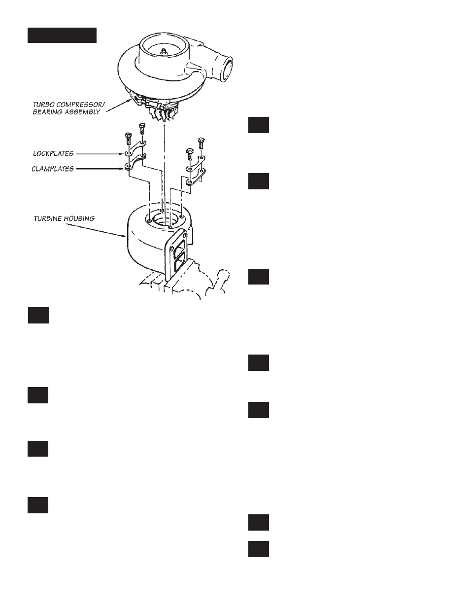
Clamp the turbine inlet flange of the
turbocharger in a bench vise. Loosen the
four bolts attaching the turbine housing to the
center bearing section of the turbocharger. See
Figure 2
.
Remove the bolts, lock plates, and clamp
plates. Carefully remove the center bearing
and compressor assembly from the cast iron
turbine housing. If the turbocharger has been
in service for some time, rust and carbon may
prevent the center bearing and compressor
assembly from easily separating from the turbine
housing. If light hammer blows, penetrating oil or
heat will not free the compressor assembly from
the turbine housing, the clamp bolt adjacent to
the turbo oil inlet connection may be backed out
so as to push against the bearing casting and
separate the two components. Remove any loose
rust or carbon from the bearing housing that
might prevent proper engagement into the new
turbine housing.
Install the center bearing and compressor
assembly into the new turbine housing.
Apply a dab of anti-seize compound to the bolts,
and then install bolts, clamp plates, and lock
plates finger-tight to allow for final positioning.
Remove the exhaust outlet adapter from the
rear of the turbine housing. Using the new
gasket provided install the turbo exhaust outlet
adapter to the turbine housing with five 8mm x
20mm metric hex bolts. Apply a dab of anti-seize
compound to the bolts, then torque the bolts to
11.3 N-m (100 in/lbs.).
TURBOCHARGER INSTALLATION
Install the new turbine inlet gasket provided
and apply a dab of anti-seize compound
to the four turbo mounting studs. Install the
turbocharger on the exhaust manifold. As the
turbocharger is reinstalled, slip the oil drain tube
into the drain hose. Tighten the turbocharger
mounting nuts to 24 ft-lbs. Tighten the oil drain
hose clamp
.
Align the compressor outlet with the
intercooler hose adapter and tighten the
clamp. Tighten the turbine housing clamp plate
bolts to 11.3N-m (100 in-lb.) torque.
Spin the turbocharger shaft to make sure
it turns freely. If not, loosen the turbine
clamp plate bolts and check for misalignment
between the turbine housing and turbocharger
center section. Retighten bolts and check again.
NOTE: If alignment cannot be achieved by
loosening and retightening the bolts, it may be
necessary to clean rust or deposits from the
engaging portion of the center bearing housing.
Refer back to step 13.
Reconnect and tighten the turbo oil .
Install the air inlet tube (from the aircleaner
housing) and the turbo exhaust pipe
onto the turbocharger. Reattach the wastegate
actuator boost line using a crimp lock clamp
10.
11.
12.
13.
15.
16.
17.
18.
19.
20.
14.
Figure 2
P.N. 96398
4