Installation procedure – Banks Power Cummins Motorhomes: (Diesel ’98 - 03 ISB 5.9L) PowerPack TLC & Stinger TLC systems w_OttoMind Module 5.9L, Class-A MHExcept Comon Rail User Manual
Page 3
INSTALLATION pROCEDURE
TURBOCHARGER REMOVAL
Loosen the clamp that attaches the air inlet
tube to the inlet for the turbocharger, and
remove the hose from the inlet.
Loosen the upper hose clamp on the
turbocharger oil drain-tube hose, located
between the two sections of the oil drain tube.
3.
Disconnect the oil supply hose at the
turbocharger.
Note the orientation of the compressor
housing in the vehicle. When the new
assembly is installed the orientation of the
compressor outlet should remain the same.
Remove the turbocharger mounting nuts and the
turbocharger from the exhaust manifold.
Clean and inspect the exhaust flange
mounting surfaces on the exhaust manifold.
Make sure the surface is clean and dry.
CAUTION: Anytime the turbocharger
is removed from the engine, take care
that no foreign objects enter any of the
turbocharger connections on the engine or
the turbocharger. Foreign objects entering air,
exhaust, or oil connections may cause major
damage to the engine and/or turbocharger
and is not covered under any warranty. Cover
the open end of the intercooler pipe with a
rag, as this pipe is very susceptible to foreign
object entry.
THERMOCOUPLE INSTALLATION
Clean and inspect the exhaust flange
mounting surfaces on the exhaust manifold.
Make sure the surface is clean and dry.
Stuff a small shop towel or rag 4 to 5 inches
into the rear exhaust manifold passage
through the turbocharger mounting flange. This is
to prevent chips from entering the manifold while
drilling and tapping.
The Cummins ISB engine uses a divided exhaust
manifold and turbocharger. The thermocouple
must be installed to sample exhaust temperature
in the rear exhaust passage (toward the flywheel).
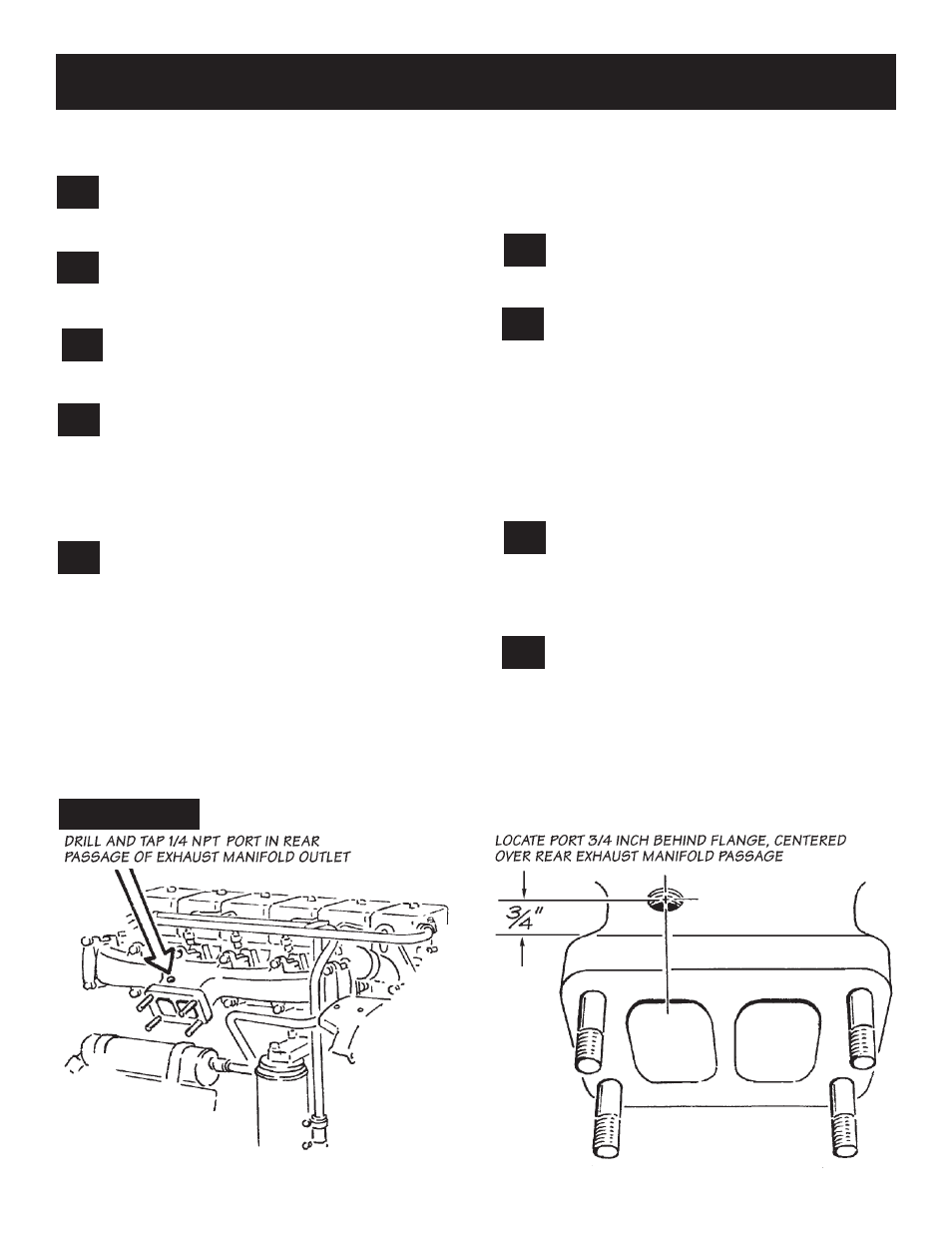
Drill through the exhaust manifold
into the rear passage at the location
shown in
Figure 1
. Use a
7
⁄
16
” drill, keeping
the drill perpendicular to the manifold
surface.
Tap the drilled hole with a
1
⁄
4
” NPT pipe
tap. Check the thread depth as you tap
by periodically removing the tap and screwing
the thermocouple into the tapped hole. The
thermocouple should thread in 3 to 3
1
⁄
2
turns hand
tight. Do not install the probe in place at this time.
9.
8.
7.
6.
5.
4.
2.
1.
Figure 1
P.N. 96398
3