Banks Power Dodge Trucks: (Diesel ’98 - 02 5.9L Cummins ISB) Power Systems- Stinger & Git-Kit Systems (does not connect to pump wire) User Manual
Page 8
the original locknuts.
20.
Turn the rod end link on the
threads of the actuator rod until the
hole lines up with the pin on the
wastegate arm. Turn the rod end
clockwise an additional six full turns,
such that it will add preload to the
wastegate.
21.
Apply a regulated supply of air
pressure to the nipple of the actuator
until the rod extends enough to slip
over the wastegate arm. Reinstall the
E-clip on the wastegate arm. Tighten
all bolts and nuts that remain loose.
turBocHarger inStallation
Note: Some turbos are mounted
with four studs protruding from the
exhaust manifold while others have
two studs in the manifold and two in
the factory turbine housing.
22.
Install the new turbine inlet
gasket provided and apply a dab
of anti-seize compound to the
four turbo mounting studs. Install
the turbocharger on the exhaust
manifold. As the turbocharger is
reinstalled, slip the oil drain tube
into the drain hose. Tighten the
turbocharger mounting nuts to 24
ft-lbs. Tighten the oil drain hose
clamp.
23.
Reconnect and tighten the turbo
oil supply hose.
24.
Re-install the air filter housing
that was previously removed.
eXHauSt inStallation
25.
Position the new Banks Monster
T.O.P. (turbine outlet pipe) onto the
turbine outlet elbow. See Figure
2
.
Install the attaching bolts to hold it in
place, but do not tighten them yet.
26.
Place a 4” muffler clamp onto
the outlet of the turbine outlet pipe,
and then slide the intermediate pipe
into the hanger at the transmission
mount, and onto the turbine outlet
pipe. Note: on extended cab short
bed models, it maybe necessary to
shorten the intermediate pipe. Install
the muffler and tailpipe without
clamps and determine how much to
trim based on the hanger position.
27.
On extended cab/quad-cab long
bed models only, position another
4” clamp onto the outlet end of the
intermediate pipe, and install the
extension pipe onto the intermediate
pipe.
28.
Install the muffler assembly
onto the end of the extension or
intermediate pipe. Temporarily
support the muffler and install the
hanger clamp at the front of the
muffler. Snug the nuts, but do not
fully tighten them.
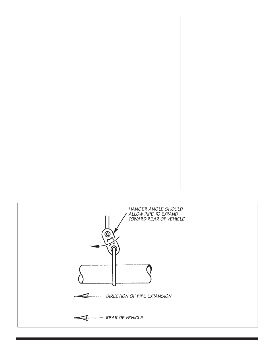
Figure 3
8 |
9 6 7 6 5 v . 5 . 0