Banks Power Ford Trucks: (Gas ’99 - 11 6.8L V10; 6.2L V8) Power Systems- PowerPack & Stinger '99-04 F250_F350 6.8L V10 (Pickups & Excursions) User Manual
Page 9
the 8” cable ties provided. from the
outside of the frame rail, remove the
bolt and captured nut from the sway
bar bracket. Bolt the heatshield and
heatshield bracket in place using the
5
⁄
16
” - 18 x 1” bolt, washers and nylock
nut at the forward tab location,
1
⁄
4
” -
20 x
5
⁄
8
” bolt, washers and crimplock
nut and the factory bolt and captured
nut in its original location.
24.
On the right side of the vehicle,
remove the front hub actuator line
from its clip on the inside of the shock
tower. Using the cable ties provided,
tie the actuator line to the brake line.
using the blanket heatshield and wire
ties provided, cover both the actuator
and the brake line.
25.
locate the right front sway bar
link. remove the link from the vehicle
by loosening the through bolts at the
upper and lower mounting locations
of the link. save hardware for reuse in
step 27.
Note: The upper through bolt is
pressed into the link.
26.
remove the upper bolt from
the link using a light press or similar
device. install the supplied heatshield
between the bolt head and stock
heatshield. reinstall the upper bolt
into the link using a light press or
similar device.
27.
reinstall the link and hand-
tighten the through bolts. orient the
heatshield to shield the top of the link
as shown in Figure 4. Tighten through
bolts to 85 ft-lbs.
28.
Install and tighten the oxygen
sensors into the threaded bungs
provided on the Y-pipe and extension.
Use a small amount of anti seize on
the threads of the oxygen sensors. Be
careful to not get any anti-seize on the
sensor elements themselves.
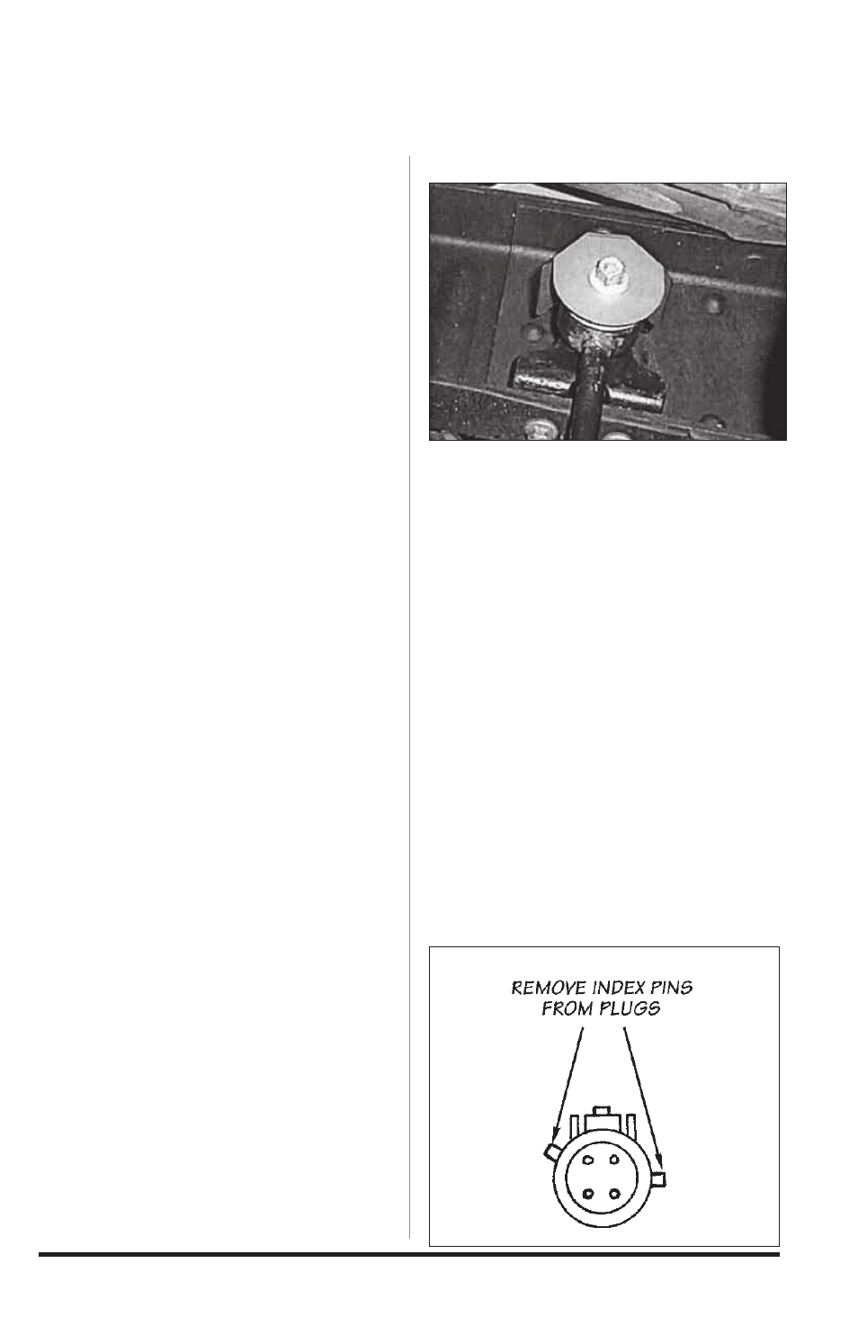
29.
Reconnect the left side oxygen
sensor to the vehicle wiring harness.
On the right side an extension will
be required. on the connector of
the oxygen sensor and on the male
connector on the sensor extension
lead, remove the two index pins on
the connector shell, by cutting or filing.
Be careful not to damage the locking
mechanism of the connectors. see
Figure 5. Plug the oxygen sensor lead
into the extension and the extension
into the vehicle wiring harness. secure
the leads away from any pipes or
moving linkages with the cable ties
provided.
30.
reinstall the front inner fender
wells. Be sure to reattach the vacuum
reservoir and all the wiring clips
previously removed. reinstall the front
wheels.
-END, SECTION 1-
Figure 4
Figure 5
96395 v.6.0
9