Banks Power Ford Trucks: (Gas ’99 - 11 6.8L V10; 6.2L V8) Power Systems- PowerPack & Stinger '99-04 F250_F350 6.8L V10 (Pickups & Excursions) User Manual
Page 6
For Stinger installation, proceed
to step 26.
1.
raise the vehicle using a hoist of
a jack and properly rated jack stands.
remove both front wheels.
2.
unbolt the front inner fender wells
and remove from the vehicle. The left
fender well will have various electrical
connectors clipped to it that must be
removed. The right fender well has
a vacuum reservoir attached with
three nuts. once these components
are detached from the fender wells
and the fender wells themselves are
removed, the components can remain
in their place until the fender wells are
reinstalled.
3.
Locate the oxygen sensors in each
exhaust headpipe, downstream of
the factory exhaust manifolds. Unplug
the connectors and remove both the
oxygen sensors. Mark the sensors for
correct reinstallation.
4.
Disconnect the three-bolt flange
at the front of the catalytic converter
from the factory y-pipe assembly.
Disconnect the headpipes from the
exhaust manifolds and remove the
y-pipe assembly from the vehicle.
5.
On vehicles with EGR system:
On the driver’s side of the engine,
unscrew the eGr tube from the
exhaust manifold with a 1
1
⁄
4
” wrench
and remove the eGr tube from the
manifold.
6.
Pull out the dipstick and remove
the small bolt that attaches the oil pan
dipstick tube to the cylinder head. Pull
the dipstick tube up and out of the
engine block. check to see if there is
an o-ring on the tube. If not, the o-ring
may be stuck inside the hole in the
engine block. This o-ring should be
retrieved if necessary and placed back
onto the tube before reinstalling it.
7.
To remove the exhaust manifolds,
use a wrench or socket to back the
nuts away from the manifolds at least
one turn, then use a 5mm 6 point
socket to remove each stud from
the head. As an alternate method,
take the nuts off the studs, and then
remove the studs.
8.
after the manifolds have been
removed from the vehicle, remove
any remaining studs from the heads.
The studs must be removed from the
heads in order to install the Banks
TorqueTubes.
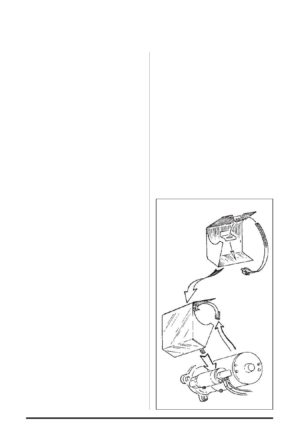
9.
install the starter heatshield onto
the starter using the #52 hose clamp
provided. See Figure 2.
Section 1
TORquETuBE MAnIFOlDS
Figure 2
6
96395 v.6.0