40eps16pbf high voltage series, Vishay high power products, Input rectifier diode, 40 a – C&H Technology 40EPS16PbF High Voltage Series User Manual
Page 4
Document Number: 94344
For technical questions, contact: [email protected]
www.vishay.com
Revision: 23-Apr-08
3
40EPS16PbF High Voltage Series
Input Rectifier Diode, 40 A
Vishay High Power Products
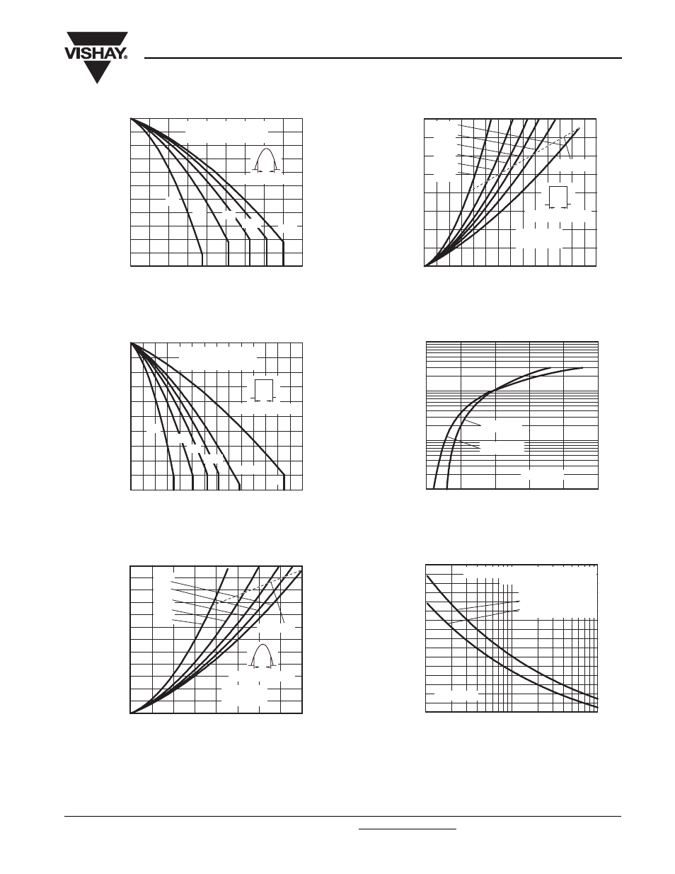
Fig. 1 - Current Rating Characteristics
Fig. 2 - Current Rating Characteristics
Fig. 3 - Forward Power Loss Characteristics
Fig. 4 - Forward Power Loss Characteristics
Fig. 5 - Forward Voltage Drop Chacteristics
Fig. 6 - Maximum Non-Repetitive Surge Current
130
125
120
115
110
105
100
95
135
140
150
145
Maximum Allowable Ca
s
e
Temperature (°C)
Average Forward Current (A)
45
35
40
30
25
20
15
10
5
0
30°
60°
90°
120°
180°
40EPS16
R
thJC
(DC) = 0.6 K/W
Conduction angle
Ø
150
140
130
120
110
100
Maximum Allowable Ca
s
e
Temperature (°C)
Average Forward Current (A)
10
20
60
70
30
40
50
0
DC
30°
60°
90°
120°
180°
40EPS16
R
thJC
(DC) = 0.6 K/W
Ø
Conduction period
5
0
30
35
50
55
60
45
40
25
20
15
10
Maximum Avera
g
e Forward
Power Lo
ss
(W)
Average Forward Current (A)
10
5
15
20
40
25
30
35
0
RMS limit
180°
120°
90°
60°
30°
40EPS16
T
J
= 150 °C
Conduction angle
Ø
50
60
70
80
40
30
20
10
0
Maximum Avera
g
e Forward
Power Lo
ss
(W)
Average Forward Current (A)
10
20
60
70
30
40
50
0
DC
180°
120°
90°
60°
30°
RMS limit
40EPS16
T
J
= 150 °C
Ø
Conduction period
1
10
100
1000
In
s
tantaneou
s
Forward Current (A)
Instantaneous Forward Voltage (V)
0.5
1.5
2.5
T
J
= 25 °C
T
J
= 150 °C
40EPS16
500
450
400
350
300
250
200
150
100
Peak Half
S
ine Wave
Forward Current (A)
Pulse Train Duration (s)
1
0.01
0.1
40EPS16
versus pulse train duration.
Initial T
J
= 150 °C
No voltage reapplied
Rated V
RRM
reapplied
Maximum non-repetitive surge current