8ews..spbf high voltage series, Vishay high power products, Surface mountable input rectifier diode, 8 a – C&H Technology 8EWS..SPbF High Voltage Series User Manual
Page 3
www.vishay.com
For technical questions, contact: [email protected]
Document Number: 94349
2
Revision: 22-Jul-08
8EWS..SPbF High Voltage Series
Vishay High Power Products
Surface Mountable
Input Rectifier Diode, 8 A
Note
(1)
When mounted on 1" square (650 mm
2
) PCB of FR-4 or G-10 material 4 oz. (140 µm) copper 40 °C/W
For recommended footprint and soldering techniques refer to application note #AN-994
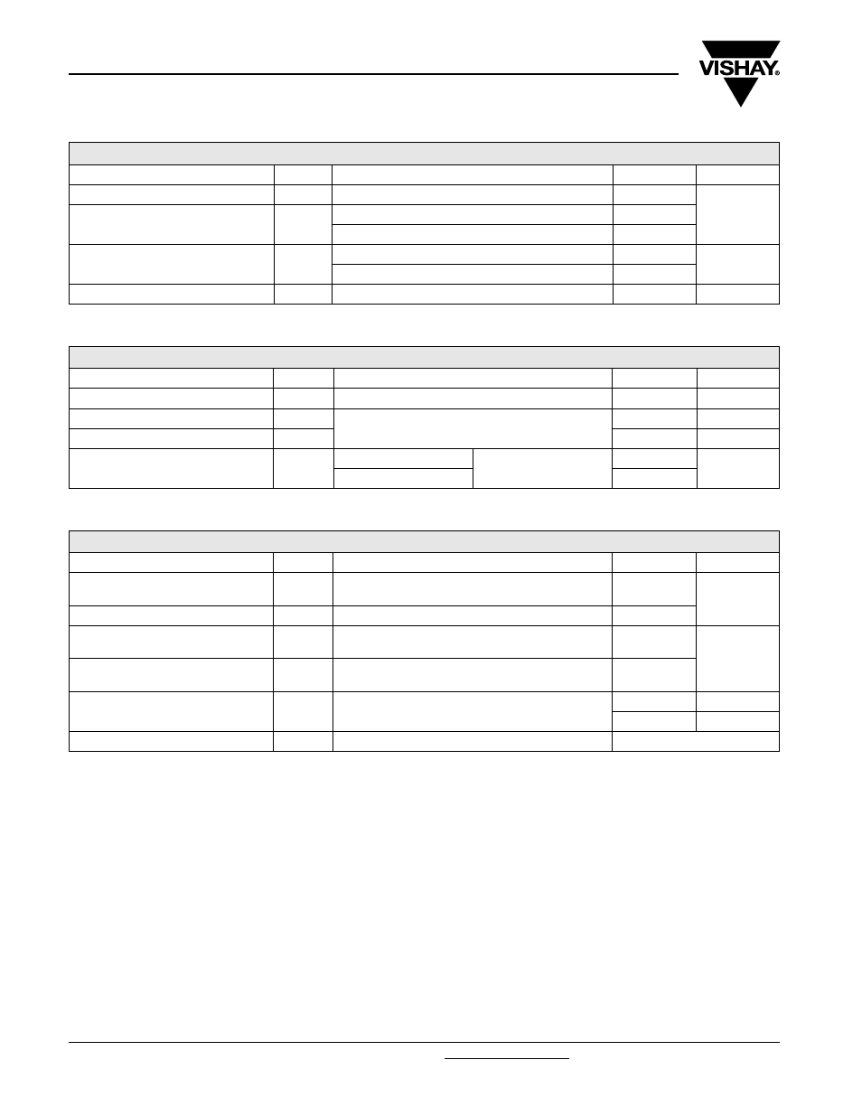
ABSOLUTE MAXIMUM RATINGS
PARAMETER SYMBOL
TEST
CONDITIONS
VALUES
UNITS
Maximum average forward current
I
F(AV)
T
C
= 105 °C, 180 ° conduction half sine wave
8
A
Maximum peak one cycle
non-repetitive surge current
I
FSM
10 ms sine pulse, rated V
RRM
applied
170
10 ms sine pulse, no voltage reapplied
200
Maximum I
2
t for fusing
I
2
t
10 ms sine pulse, rated V
RRM
applied
130
A
2
s
10 ms sine pulse, no voltage reapplied
145
Maximum I
2
√t for fusing
I
2
√t
t = 0.1 to 10 ms, no voltage reapplied
1450
A
2
√s
ELECTRICAL SPECIFICATIONS
PARAMETER SYMBOL
TEST
CONDITIONS
VALUES
UNITS
Maximum forward voltage drop
V
FM
8 A, T
J
= 25 °C
1.1
V
Forward slope resistance
r
t
T
J
= 150 °C
20
m
Ω
Threshold voltage
V
F(TO)
0.82
V
Maximum reverse leakage current
I
RM
T
J
= 25 °C
V
R
= Rated V
RRM
0.05
mA
T
J
= 150 °C
0.50
THERMAL - MECHANICAL SPECIFICATIONS
PARAMETER SYMBOL
TEST
CONDITIONS
VALUES
UNITS
Maximum junction and storage
temperature range
T
J
, T
Stg
- 55 to 150
°C
Soldering temperature
T
S
240
Maximum thermal resistance,
junction to case
R
thJC
DC
operation
2.5
°C/W
Typical thermal resistance,
junction to ambient (PCB mount)
R
thJA
(1)
62
Approximate weight
1
g
0.03
oz.
Marking device
Case style D-PAK (TO-252AA)
8EWS12S