Vishay bccomponents – C&H Technology 102 PHR-ST User Manual
Page 3
Document Number: 28371
For technical questions, contact:
www.vishay.com
Revision: 03-May-10
169
101/102 PHR-ST
Aluminum Capacitors
Power High Ripple Current Screw Terminals
Vishay BCcomponents
6800
-
-
35 x 60
35 x 105
65 x 105
76 x 105
-
-
76 x 146
76 x 220
-
-
35 x 80
50 x 80
76 x 105
76 x 146
76 x 146
76 x 146
-
90 x 146
10 000
-
35 x 60
35 x 80
50 x 80
76 x 105
76 x 105
76 x 220
-
-
-
-
-
35 x 105
50 x 105
76 x 146
76 x 146
90 x 146
-
-
90 x 220
15 000
35 x 60
35 x 60
35 x 105
50 x 105
76 x 146
76 x 146
-
-
-
-
-
35 x 80
50 x 80
-
-
-
90 x 220
-
-
-
22 000
35 x 60
35 x 80
50 x 80
65 x 105
76 x 220
76 x 220
-
-
-
-
-
50 x 80
50 x 105
76 x 105
90 x 146
90 x 146
-
-
-
-
33 000
35 x 80
35 x 105
50 x 105
76 x 105
-
-
-
-
-
-
50 x 80
50 x 80
65 x 105
76 x 146
90 x 220
90 x 220
-
-
-
-
47 000
35 x 105
50 x 80
65 x 105
-
-
-
-
-
-
-
50 x 80
50 x 105
76 x 105
76 x 146
-
-
-
-
-
-
68 000
50 x 80
50 x 105
76 x 105
76 x 146
-
-
-
-
-
-
50 x 105
65 x 105
76 x 146
-
-
-
-
-
-
-
100 000
50 x 105
65 x 105
-
76 x 220
-
-
-
-
-
-
65 x 105
76 x 105
76 x 146
90 x 146
-
-
-
-
-
-
150 000
65 x 105
76 x 105
76 x 146
-
-
-
-
-
-
-
76 x 105
76 x 146
-
90 x 220
-
-
-
-
-
-
220 000
65 x 105
-
76 x 220
-
-
-
-
-
-
-
76 x 105
76 x 146
90 x 146
-
-
-
-
-
-
-
330 000
76 x 146
76 x 220
-
-
-
-
-
-
-
-
-
90 x 146
90 x 220
-
-
-
-
-
-
-
470 000
76 x 220
-
-
-
-
-
-
-
-
-
90 x 146
90 x 220
-
-
-
-
-
-
-
-
680 000
76 x 220
-
-
-
-
-
-
-
-
-
1 000 000
90 x 220
-
-
-
-
-
-
-
-
-
SELECTION CHART FOR C
R
, U
R
AND RELEVANT NOMINAL CASE SIZES (Ø D x L in mm)
C
R
(µF)
U
R
(V)
25
40
63
100
200
250
350
385
400
450
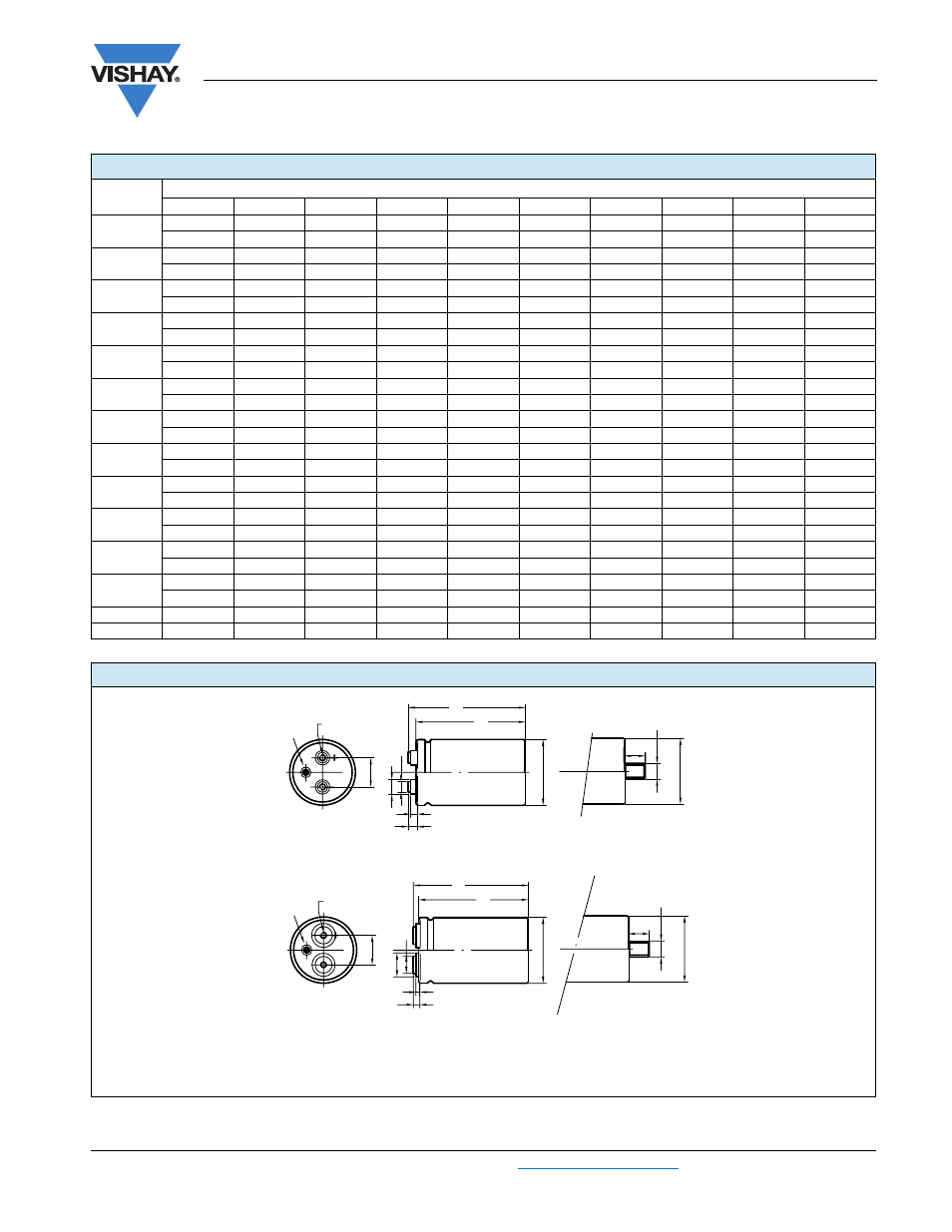
DIMENSIONS in millimeters AND AVAILABLE FORMS
Maximum permissible torque which may be applied to the termination screws: 2 Nm for M5; 2.5 Nm for M6
For accessories refer to datasheet “Mounting Accessories”.
The capacitors are delivered with screws and washers.
A
P
Safety
Vent
Thread M x S
M
b
D
D
L
L
t
H
T
B
d1
l
b
Fig. 2A: Standard M5 disc: screw terminal (ST) and screw terminal bolt nut (STB)
B
P
Safety
Vent
Thread M x S
M
b
D
D
H
T
B
d
1
l
b
L
L
t
Fig. 2B: High current M6 disc: screw terminal (ST) and screw terminal bolt nut (STB)