Electrical characteristics @ t, 25°c (unless otherwise specified), Switching characteristics @ t – C&H Technology 20MT120UF User Manual
Page 3: Parameters min typ max units test conditions
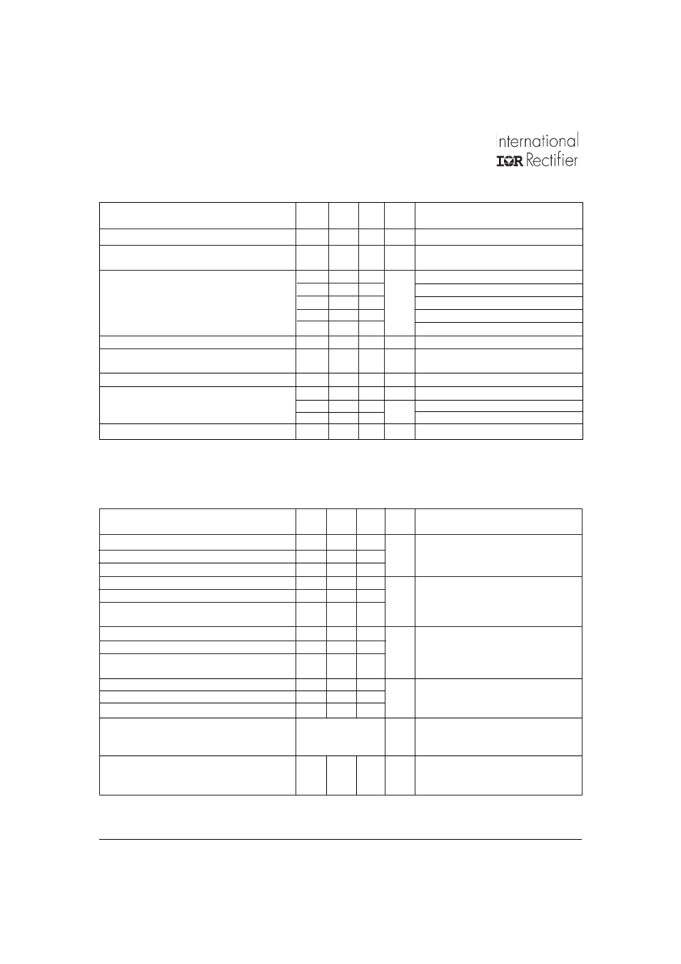
20MT120UF
I27124 rev. D 02/03
V
(BR)CES
Collector-to-Emitter Breakdown Voltage 1200
V
V
GE
= 0V, I
C
= 250µA
∆V
(BR)CES
/ Temperature Coeff. of
+1.3
V/°C
V
GE
= 0V, I
C
= 3mA (25-125°C)
∆T
J
Breakdown Voltage
V
CE(ON)
Collector-to-Emitter Saturation Voltage
3.29
3.59
V
V
GE
= 15V, I
C
= 20A
4.42
4.66
V
GE
= 15V, I
C
= 40A
3.87
4.11
V
GE
= 15V, I
C
= 20A T
J
= 125°C
5.32
5.70
V
GE
= 15V, I
C
= 40A T
J
= 125°C
3.99
4.27
V
GE
= 15V, I
C
= 20A T
J
= 150°C
V
GE(th)
Gate Threshold Voltage
4
6
V
V
CE
= V
GE
, I
C
= 250µA
∆V
GE(th)
/ Temperature Coeff. of
-14
mV/°C V
CE
= V
GE
, I
C
= 3mA (25-125°C)
∆T
J
Threshold Voltage
g
fe
Transconductance
17.5
S
V
CE
= 50V, I
C
= 20A, PW = 80µs
I
CES
Zero Gate Voltage Collector Current
(1)
250
µA
V
GE
= 0V, V
CE
= 1200V, T
J
= 25°C
0.7
3.0
mA
V
GE
= 0V, V
CE
= 1200V, T
J
= 125°C
2.9
9.0
V
GE
= 0V, V
CE
= 1200V, T
J
= 150°C
I
GES
Gate-to-Emitter Leakage Current
±250
nA
V
GE
= ± 20V
Electrical Characteristics @ T
J
= 25°C (unless otherwise specified)
Parameters
Min Typ Max Units Test Conditions
Q
g
Total Gate Charge (turn-on)
176
264
nC
I
C
= 20A
Q
ge
Gate-Emitter Charge (turn-on)
19
30
V
CC
= 600V
Q
gc
Gate-Collector Charge (turn-on)
89
134
V
GE
= 15V
E
on
Turn-On Switching Loss
513
770
µJ
V
CC
= 600V, I
C
= 20A
E
off
Turn-Off Switching Loss
402
603
V
GE
= 15V, R
g
= 5
Ω, L = 200µH
E
tot
Total Switching Loss
915
1373
T
J
= 25°C, Energy losses include tail
and diode reverse recovery
E
on
Turn-On Switching Loss
930
1395
µJ
V
CC
= 600V, I
C
= 20A
E
off
Turn-Off Switching Loss
610
915
V
GE
= 15V, R
g
= 5
Ω, L = 200µH
E
tot
Total Switching Loss
1540
2310
T
J
= 125°C, Energy losses include tail
and diode reverse recovery
C
ies
Input Capacitance
2530
3790
pF
V
GE
= 0V
C
oes
Output Capacitance
344
516
V
CC
= 30V
C
res
Reverse Transfer Capacitance
78
117
f = 1.0 MHz
RBSOA
Reverse Bias Safe Operating Area
full square
T
J
= 150°C, I
C
= 120A
V
CC
= 1000V, V
p
= 1200V
R
g
= 5
Ω, V
GE
= +15V to 0V
SCSOA
Short Circuit Safe Operating Area
10
µs
T
J
= 150°C
V
CC
= 900V, V
p
= 1200V
R
g
= 5
Ω, V
GE
= +15V to 0V
Switching Characteristics @ T
J
= 25°C (unless otherwise specified)
Parameters
Min Typ Max Units Test Conditions
(1)
I
CES
includes also opposite leg overall leakage
Document Number: 93588
www.vishay.com
2