301u(r) series – C&H Technology 309U(R) Series User Manual
Page 16
301U(R) Series
7
www.irf.com
Bulletin I2032 rev. B 03/03
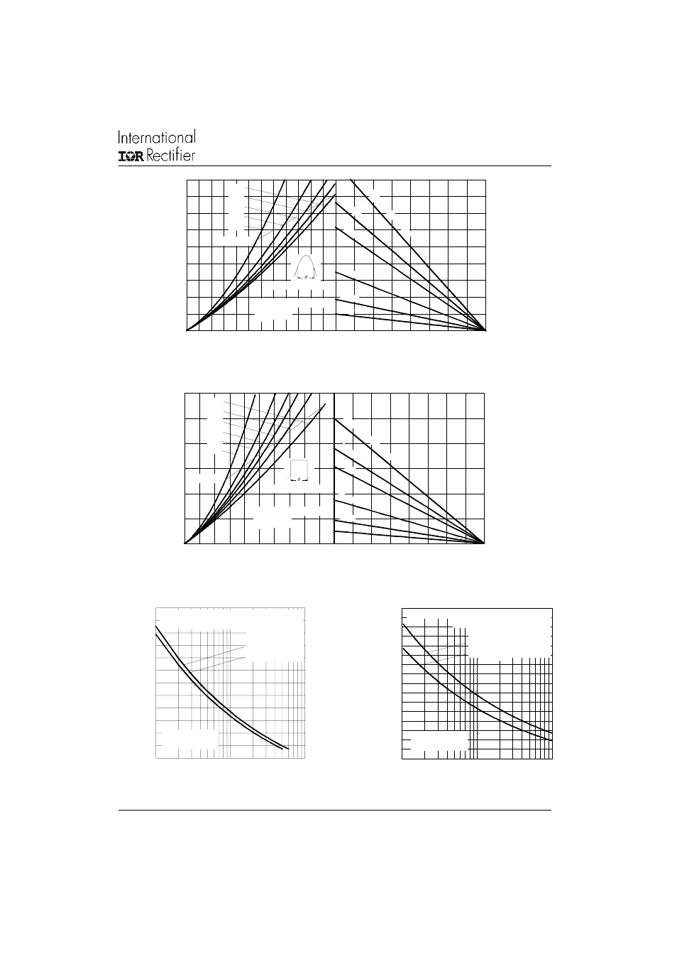
20
40
60
80
100 120 140 160 180
Maximum Allowable Ambient Temperature (°C)
R
= 0
.1
K
/W
- D
e
lta
R
th
SA
0.2
K
/ W
0.3
K/
W
1.5 K/W
3 K/ W
0.7 K
/ W
0
50
100
150
200
250
300
350
400
450
0
50
100
150
200
250
300
180°
120°
90°
60°
30°
RMS Limit
Conduc tion Angle
M
a
xi
m
u
m
A
v
e
rag
e
F
o
rw
a
rd P
o
we
r L
o
ss
(
W
)
Average Forward Current (A)
T = 180°C
301U(R) Series (2500V)
J
Fig. 7 - Forward Power Loss Characteristics
Fig. 8 - Forward Power Loss Characteristics
20
40
60
80
100 120 140 160 180
Maximum Allowable Ambient Temperature (°C)
R
=
0.
1 K
/ W
- D
elta
R
th
SA
0.2
K/
W
0.3
K/
W
1.5 K/W
3 K/W
0.7 K/
W
0
100
200
300
400
500
600
0
100
200
300
400
500
DC
180°
120°
90°
60°
30°
RMS Limit
Conduction Period
M
a
xi
m
u
m
A
v
er
age
F
o
rw
a
rd
P
o
w
e
r L
o
ss
(
W
)
Average Forward Current (A)
T = 180°C
301U(R) Series (2500V)
J
2000
3000
4000
5000
6000
7000
8000
1
10
100
Numb er Of Eq ua l Amplitude Half Cyc le Current Pulses (N)
P
e
ak
H
a
lf S
in
e
W
a
v
e
F
o
rw
ar
d
C
u
rr
e
n
t (
A
)
Initial T = 180°C
@ 60 Hz 0.0083 s
@ 50 Hz 0.0100 s
At Any Rated Load Condition And With
Rated V Applied Following Surge.
RRM
J
301U(R) Series
(1600V to 2000V)
Fig. 9 - Maximum Non-Repetitive Surge Current
Fig. 10 - Maximum Non-Repetitive Surge Current
1000
2000
3000
4000
5000
6000
7000
8000
9000
0.01
0.1
1
Pulse Train Duration (s)
Pe
a
k
H
a
lf
S
in
e
W
a
v
e
F
o
rw
ar
d
C
u
rr
e
n
t (
A
)
Versus Pulse Train Duration.
Initial T = 180 °C
No Voltage Reapplied
Rated V Reapplied
Maximum Non Repetitive Surge Current
RRM
J
301U(R) Series
(1600V to 2000V)