301u(r) series – C&H Technology 309U(R) Series User Manual
Page 12
301U(R) Series
3
www.irf.com
Bulletin I2032 rev. B 03/03
∆
R
thJC
Conduction
(The following table shows the increment of thermal resistence R
thJC
when devices operate at different conduction angles than DC)
80 to 200
250
00 to 200
250
180°
0.015
0.015
0.011
0.011
120°
0.018
0.018
0.019
0.019
90°
0.023
0.023
0.025
0.025
K/W
T
J
= T
J
max.
60°
0.034
0.034
0.035
0.035
30°
0.056
0.056
0.057
0.057
Sinusoidal conduction Rectangular conduction
Conduction angle
Units
Conditions
T
J
Max. junction operating temperature range
-40 to 180
T
stg
Max. storage temperature range
-40 to 200
R
thJC
Max. thermal resistance, junction to case
0.14
DC operation
R
thCS
Max. thermal resistance, case to heatsink
0.08
Mounting surface, smooth, flat and greased
T
Max. allowed mounting torque +0 -20%
37
Not lubricated threads
28
Lubricated threads
wt
Weight
301U
250 ± 5
303U
152 ± 5
305U
177 ± 5
g
307U
197 ± 5
309U
160 ± 5
Case style
DO-205AB (DO-9)
See Outline Table
Parameter
301U(R)
Units
Conditions
Thermal and Mechanical Specifications
°C
K/W
Nm
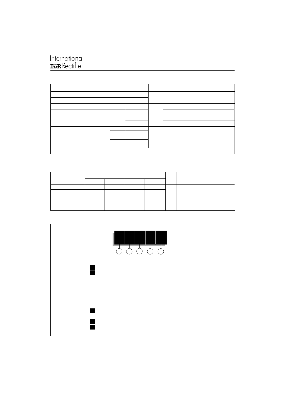
Ordering Information Table
30
1
U
A
250
1
2
3
4
5
Device Code
1
-
30
= Essential Part Number
2
-
1
= Standard Device
3
= Top Threaded version
5
= Type for rotating application with Top Threaded
version 3/8 16UNC-2A
7
= Type for rotating application with flexible lead
9
= Type for rotating application with Top Threaded
version 3/8 24UNF
3
-
U
= Stud Normal Polarity (Cathode to Stud)
UR
= Stud Reverse Polarity (Anode to Stud)
4
-
A
= Max. Leakage selection I
RRM
= 2mA T
J
= 25°C
5
-
Voltage code: Code x 10=V
RRM
(See Voltage Ratings table)