Chopper igbtmod™ hvigbt module – C&H Technology CM1200E4C-34N User Manual
Page 2
Chopper IGBTMOD™
HVIGBT Module
1200 Amperes/1700 Volts
CM1200E4C-34N
Powerex, Inc., 200 E. Hillis Street, Youngwood, Pennsylvania 15697-1800 (724) 925-7272
1
8/05
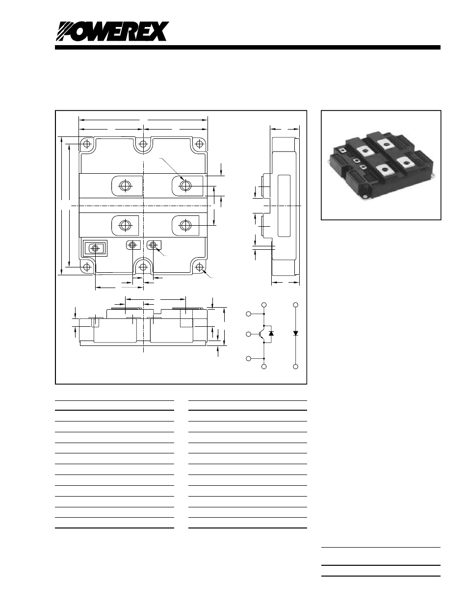
Outline Drawing and Circuit Diagram
A
D
D
F
E
C
4
2
3
E
G
C
1
B
G
H
N
T
R
4(C)
2(A)
3(E)
E
G
C
P
1(K)
Q
S
J
V
U
W
X
K (4 TYP)
M (3 TYP)
L
(6 PLACES)
Dimensions
Inches
Millimeters
A
5.19±0.02
130.0±0.5
B
5.51±0.02
140.0±0.5
C
4.88±0.01
124.0±0.25
D
2.24±0.01
57.0±0.25
E
1.57±0.008
40.0±0.2
F
0.79±0.004
20.0±0.1
G
1.92±0.008
48.8±0.2
H
0.42±0.008
10.65±0.2
J
0.41±0.008
10.35±0.2
K
M8 Metric
M8
L
0.28 Dia.
7.0 Dia.
Description:
Powerex Chopper HVIGBT
Modules are designed for use
in switching applications. Each
module consists of one IGBT
Transistor having a reverse-
connected super-fast recovery
free-wheel diode and an anode-
collector connected super-fast
recovery free-wheel diode. All
components and interconnects
are isolated from the heat sinking
baseplate, offering simplifi ed
system assembly and thermal
management.
Features:
£
Low Drive Power
£
Low V
CE(sat)
£
Super-Fast Recovery
Free-Wheel Diode
£
Isolated Baseplate for Easy
Heat Sinking
Applications:
£
Traction
£
Medium Voltage Drives
£
High Voltage Power Supplies
Ordering Information:
Example: Select the complete
part module number you desire
from the table below -i.e.
CM1200E4C-34N is a 1700V
(V
CES
), 1200 Ampere Chopper
IGBTMOD™ Power Module.
Type
Current Rating
V
CES
Amperes
Volts (x 50)
CM
1200
34
Dimensions
Inches
Millimeters
M
M4 Metric
M4
N
2.42±0.012
61.5±0.3
P
1.50+0.04/-0.0 38.0+1.0/-0.0
Q
0.2±0.008
5.0±0.2
R
0.65 Min.
16.5 Min.
S
0.30 Min.
7.7 Min.
T
0.71±0.008
18.0±0.2
U
1.16±0.02
29.5±0.5
V
0.60±0.008
15.0±0.2
W
0.21±0.008
5.2±0.2
X
1.10+0.04/-0.0 28.0+1.0/-0.0