95pf(r)...(w) series, Vishay high power products – C&H Technology 95PF(R)...(W) Series User Manual
Page 5
www.vishay.com
For technical questions, contact: [email protected]
Document Number: 93532
4
Revision: 01-Oct-08
95PF(R)...(W) Series
Vishay High Power Products
Standard Recovery Diodes
Generation 2 DO-5 (Stud Version), 95 A
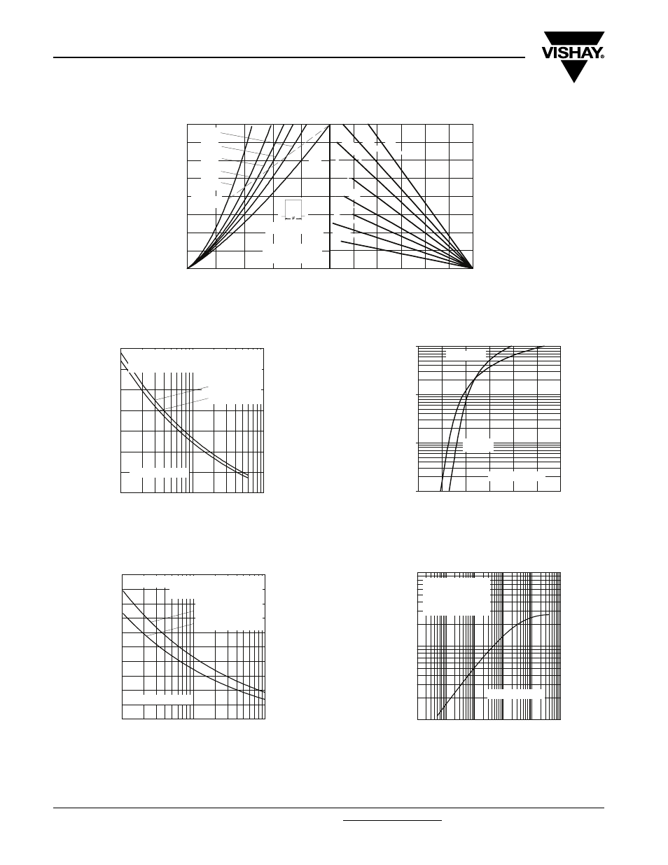
Fig. 4 - Forward Power Loss Characteristics
Fig. 5 - Maximum Non-Repetitive Surge Current
Fig. 6 - Maximum Non-Repetitive Surge Current
Fig. 7 - Forward Voltage Drop Characteristics
Fig. 8 - Thermal Impedance Z
thJC
Characteristics
Average Forward Current (A)
Maximum Allowable Forward Power Loss (W)
Maximum Allowable Ambient Temperature (°C)
0
30
60
90
120
150
180
1 K/
W
2 K/
W
0.3 K/
W
0.7 K/
W
0.5 K/
W
5 K/W
1.5 K/
W
3 K/
W
0
20
40
60
80
100
120
140
160
0
30
60
90
120
150
RMS Limit
Conduction Period
180°
120°
90°
60°
30°
95PF(R) Series
Tj = 180°C
DC
Number Of Equal Amplitude Half Cycle Current Pulses (N)
Peak Haf Sine Wave Forward Current (A)
400
600
800
1000
1200
1400
1600
1800
1
10
100
At Any Rated Load Condition And With
Rated Vrrm Applied Following Surge.
95PF(R) Series
Initial Tj = 150°C
@ 60 Hz 0.0083 s
@ 50 Hz 0.0100 s
Pulse Train Duration (s)
Peak Haf Sine Wave Forward Current (A)
200
400
600
800
1000
1200
1400
1600
1800
2000
2200
0.01
0.1
1
Maximum Non Repetitive Surge Current
Versus Pulse Train Duration.
95PF(R) Series
Initial Tj = 150°C
No Voltage Reapplied
Rated Vrrm Reapplied
Instantaneous Forward Voltage (V)
Instantaneous Forward Current (A)
1
10
100
1000
0
0.5
1
1.5
2
2.5
3
Tj = 25°C
95PF(R) Series
Tj = 180°C
Square Wave Pulse Duration (s)
Transient Thermal Impedance Z
thJC
(K/W)
0.01
0.1
1
0.0001 0.001
0.01
0.1
1
10
Steady State Value
RthJC = 0.27 K/W
(DC Operation)
95PF(R) Series