Vishay high power products, Half-bridge" igbt mtp (warp speed igbt), 114 a, Thermistor specifications – C&H Technology 50MT060WHTAPbF User Manual
Page 4: Thermal - mechanical specifications
Document Number: 94468
For technical questions, contact: [email protected]
www.vishay.com
Revision: 06-May-08
3
50MT060WHTAPbF
"Half-Bridge" IGBT MTP
(Warp Speed IGBT), 114 A
Vishay High Power Products
Notes
(1)
T
0
, T
1
are thermistor´s temperatures
(2)
, temperature in Kelvin
Notes
(1)
Standard version only i.e. without optional thermistor
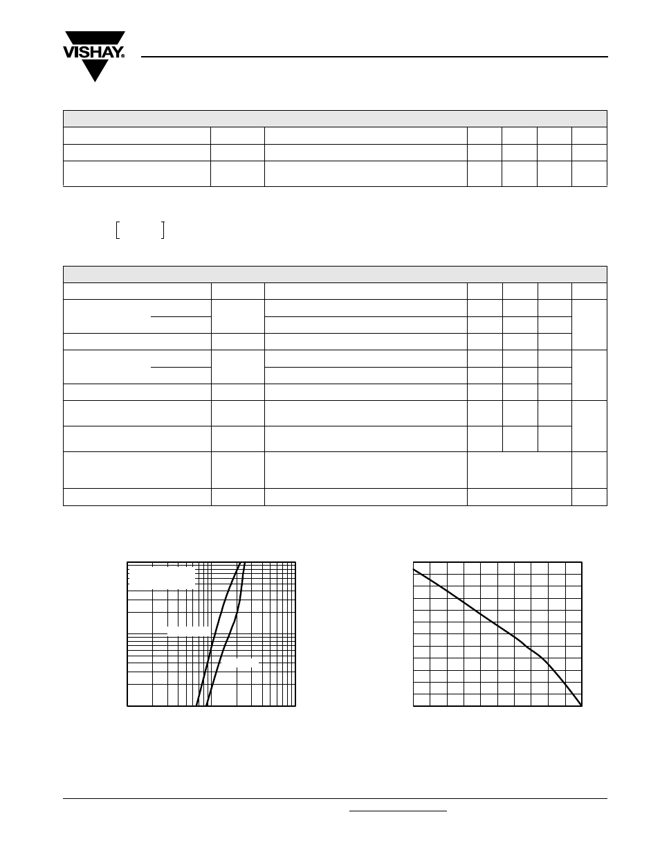
Fig. 1 - Typical Output Characteristics
Fig. 2 - Maximum Collector Current vs. Case Temperature
THERMISTOR SPECIFICATIONS
PARAMETER
SYMBOL
TEST CONDITIONS
MIN.
TYP.
MAX.
UNITS
Resistance
R
0
(1)
T
0
= 25 °C
-
30
-
k
Ω
Sensitivity index of the
thermistor material
β
(1)(2)
T
0
= 25 °C
T
1
= 85 °C
-
4000
-
K
R
0
R
1
-------
β 1
T
0
------
1
T
1
------
–
⎝
⎠
⎛
⎞
exp
=
THERMAL - MECHANICAL SPECIFICATIONS
PARAMETER
SYMBOL
TEST CONDITIONS
MIN.
TYP.
MAX.
UNITS
Operating junction
temperature range
IGBT, Diode
T
J
- 40
-
150
°C
Thermistor
- 40
-
125
Storage temperature range
T
Stg
- 40
-
125
Junction to case
IGBT
R
thJC
-
-
0.38
°C/W
Diode
-
-
0.8
Case to sink
Module
R
thCS
Heatsink compound thermal conductivity = 1 W/mK
-
0.06
-
Clearance
(1)
External shortest distance in air between
two terminals
5.5
-
-
mm
Creepage
(1)
Shortest distance along the external surface of the
insulating material between 2 terminals
8
-
-
Mounting torque to heatsink
A mounting compound is recommended and the
torque should be checked after 3 hours to allow for
the spread of the compound. Lubricated threads.
3 ± 10 %
Nm
Weight
66
g
1
100
10
I
C
- Collector to Emitter Current (A)
V
CE
- Collector to Emitter Voltage (V)
1.0
10
0.1
V
GE
= 15 V
20 µs pulse width
T
J
= 150 °C
T
J
= 25 °C
0
100
120
20
40
60
80
Maximum DC Collector Current (A)
T
C
- Case Temperature (°C)
50
75
100
125
150
25