T..hf series, Vishay high power products – C&H Technology T..HF Series User Manual
Page 9
www.vishay.com
For technical questions, contact: [email protected]
Document Number: 93587
8
Revision: 12-Jun-08
T..HF Series
Vishay High Power Products
Power Rectifier Diodes (T-Modules),
40 A/70 A/85 A/110 A
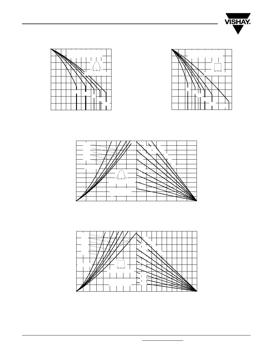
Fig. 19 - Current Ratings Characteristics
Fig. 20 - Current Ratings Characteristics
Fig. 21 - Forward Power Loss Characteristics
Fig. 22 - Forward Power Loss Characteristics
60
70
80
90
100
110
120
130
140
150
0
20
40
60
80
100
120
30°
60°
90°
120°
180°
Ma
x
imu
m
A
llo
w
a
b
le
C
a
se
T
e
m
p
e
ra
tu
re
(
°C
)
Conduc tion Angle
Average Forward Current (A)
T110HF.. Series
R (DC) = 0.47 K/ W
thJC
60
70
80
90
100
110
120
130
140
150
0
20
40
60
80 100 120 140 160 180
DC
30°
60°
90°
120°
180°
Ma
x
imu
m
A
llo
w
a
b
le
C
a
se
T
e
mp
e
ra
tu
re
(
°C
)
Conduc tion Period
T110HF.. Series
R (DC) = 0.47 K/ W
thJC
Average Forward Current (A)
0
25
50
75
100
125
150
Ma ximum Allowa ble Ambient Temperature (°C)
5 K/ W
3 K/ W
2 K/W
1.5
K/ W
1 K
/ W
0.7
K/
W
0.5
K/
W
0.3
K/
W
R
=
0.2
K/
W
-
D
e
lta
R
th
SA
0
10
20
30
40
50
60
70
80
90
100
110
120
130
0
20
40
60
80
100
120
Average Forward Current (A)
RMS Limit
M
a
x
imu
m A
v
e
ra
g
e
F
o
rw
a
rd
P
o
w
e
r L
o
ss
(
W
)
Conduc tion Angle
180°
120°
90°
60°
30°
T110HF.. Series
T = 150°C
J
0
25
50
75
100
125
150
Maximum Allowable Ambient Temperature (°C)
5 K/ W
3 K/ W
2 K/ W
1.5
K/ W
1 K/
W
0.7
K/ W
0.5
K/ W
0.3
K/W
R
=
0.2
K/
W
- D
elt
a
R
th
SA
0
20
40
60
80
100
120
140
160
180
0
20
40
60
80 100 120 140 160 180
DC
180°
120°
90°
60°
30°
RMS Limit
Conduc tion Period
Average Forward Current (A)
Ma
x
im
u
m
A
v
e
ra
g
e
F
o
rw
a
rd
P
o
w
e
r
Lo
ss
(
W
)
T110HF.. Series
T = 150°C
J