T..hf series, Vishay high power products – C&H Technology T..HF Series User Manual
Page 7
www.vishay.com
For technical questions, contact: [email protected]
Document Number: 93587
6
Revision: 12-Jun-08
T..HF Series
Vishay High Power Products
Power Rectifier Diodes (T-Modules),
40 A/70 A/85 A/110 A
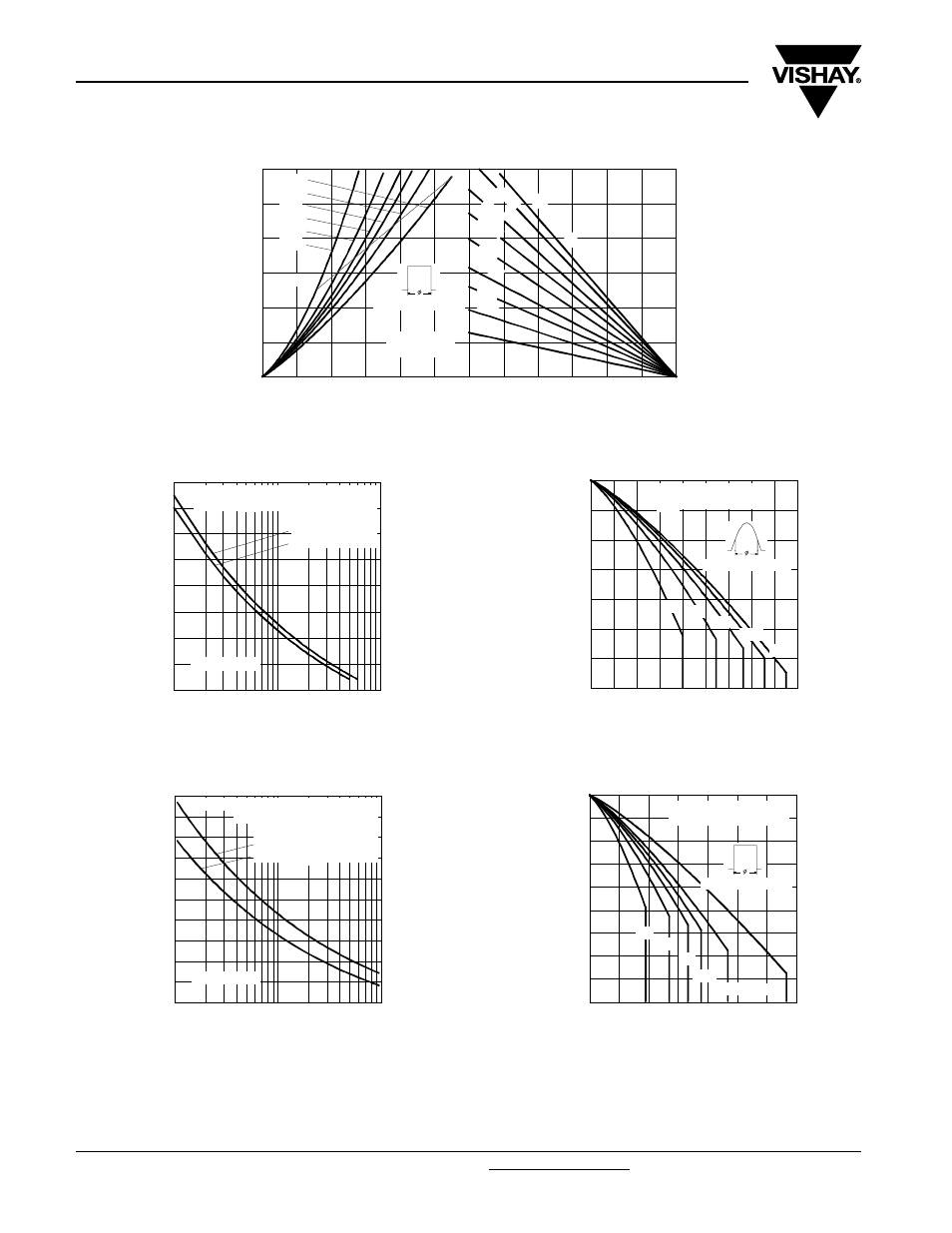
Fig. 10 - Forward Power Loss Characteristics
Fig. 11 - Maximum Non-Repetitive Surge Current
Fig. 12 - Maximum Non-Repetitive Surge Current
Fig. 13 - Current Ratings Characteristics
Fig. 14 - Current Ratings Characteristics
0
25
50
75
100
125
150
Maximum Allowable Ambient Temperature (°C)
0.5
K/
W
0.
3K
/ W
0.7
K/W
1K/
W
1.5K
/W
5K/W
3K/W
2K/W
R
=
0
.2
K/
W
-
D
e
lta
R
th
SA
0
20
40
60
80
100
120
0
20
40
60
80
100
120
DC
180°
120°
90°
60°
30°
RMS Limit
Conduc tion Period
Average Forward Current (A)
M
a
xi
m
u
m
A
v
e
rag
e
F
o
rw
ar
d P
o
w
e
r L
o
ss
(
W
)
T70HF.. Series
T = 150°C
J
300
400
500
600
700
800
900
1000
1100
1
10
100
P
e
a
k
H
a
lf
S
in
e
W
a
v
e
F
o
rw
a
rd
C
u
rr
e
n
t
(A
)
Number Of Equal Amplitude Half Cycle Current Pulses (N)
T70HF.. Series
Initial T = 150°C
@ 60 Hz 0.0083 s
@ 50 Hz 0.0100 s
At Any Ra ted Loa d Cond ition And With
Rated V App lied Following Surge.
J
RRM
200
300
400
500
600
700
800
900
1000
1100
1200
0.01
0.1
1
P
e
ak
H
a
lf
S
in
e
W
a
v
e
F
o
rw
ar
d C
u
rr
e
n
t (
A
)
Pulse Train Duration (s)
Maximum Non Repetitive Surge Current
T70HF.. Series
Initial T = 150°C
No Voltage Reapplied
Rated V Reapplied
RRM
Versus Pulse Train Duration.
J
80
90
100
110
120
130
140
150
0
10
20
30
40
50
60
70
80
90
30°
60°
90°
120°
180°
M
a
x
im
u
m A
llo
w
a
b
le
C
a
se
T
e
mp
e
ra
tu
re
(
°C
)
Conduc tion Angle
Average Forward Current (A)
T85HF.. Series
R (DC) = 0.62 K/ W
thJC
60
70
80
90
100
110
120
130
140
150
0
20
40
60
80
100
120
140
DC
30°
60°
90°
120°
180°
M
a
x
imu
m A
llo
w
a
b
le
C
a
se
T
e
mp
e
ra
tu
re
(
°C
)
Conduction Period
Average Forward Current (A)
T85HF.. Series
R (DC) = 0.62 K/ W
thJC