Vishay sfernice – C&H Technology RCH User Manual
Page 5
Document Number: 50006
For technical questions, contact: [email protected]
www.vishay.com
Revision: 09-Jun-08
4
RCH
Power Resistors, for Mounting onto a Heatsink
Thick Film Technology
Vishay Sfernice
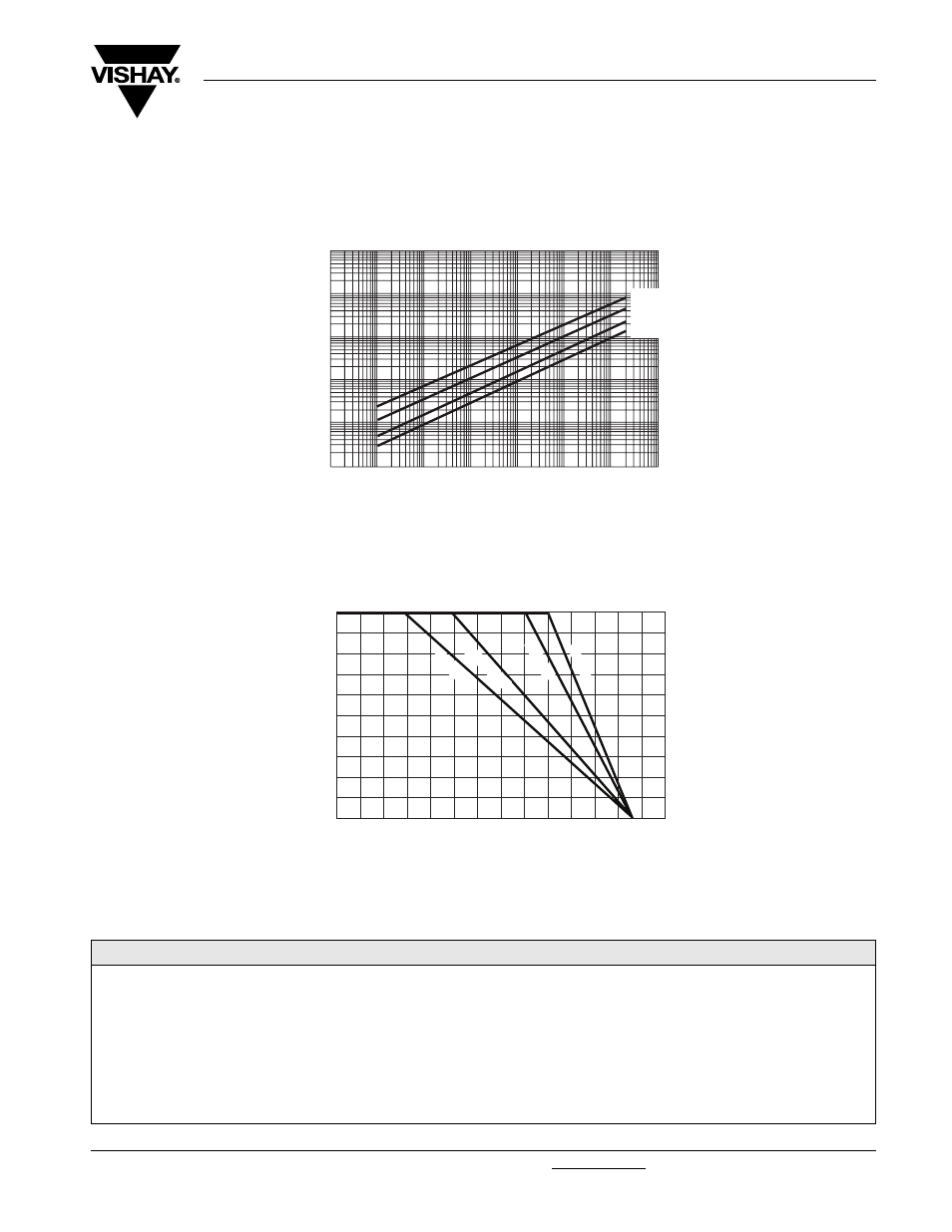
OVERLOADS
The applied voltage must always be lower than the maximum overload voltage as shown in the special features table.
The values indicated on the graph below are applicable to resistors in air or mounted onto a heatsink.
POWER RATING CHART
For resistors mounted onto heatsink and thermal resistance of 1 °C/W.
To improve the thermal conductivity, surfaces in contact should be coated with a silicone grease.
MARKING
Model, Style, Resistance Value (in
Ω), Tolerance (in %), Manufacturing Date, VISHAY trade mark.
ORDERING INFORMATION
RCH
25
3.3 k
Ω
± 5 %
R
XXX
MODEL
STYLE
RESISTANCE VALUE
TOLERANCE
Optional
± 1 %
± 2 %
± 5 %
± 10 %
CONNECTIONS
Optional
S: Flat with hole
R: Round lead
V: M2 screw
CUSTOM DESIGN
Optional
10
- 6
1000
100
10
1
0.1
ENERGY IN JOULES
OVERLOAD DURATION IN s
ENERGY CURVE
RCH 50
RCH 25
RCH 10
RCH 5
10
- 5
10
- 4
10
- 3
10
- 2
10
- 1
0
%
RA
TED PO
WER
AMBIENT TEMPERATURE IN °C
RCH 5
0
0
25
50
75
100
RCH 25
RCH 10
RCH 5
20
40
60
80
100
120
140