Vishay sfernice – C&H Technology RCH User Manual
Page 3
Document Number: 50006
For technical questions, contact: [email protected]
www.vishay.com
Revision: 09-Jun-08
2
RCH
Power Resistors, for Mounting onto a Heatsink
Thick Film Technology
Vishay Sfernice
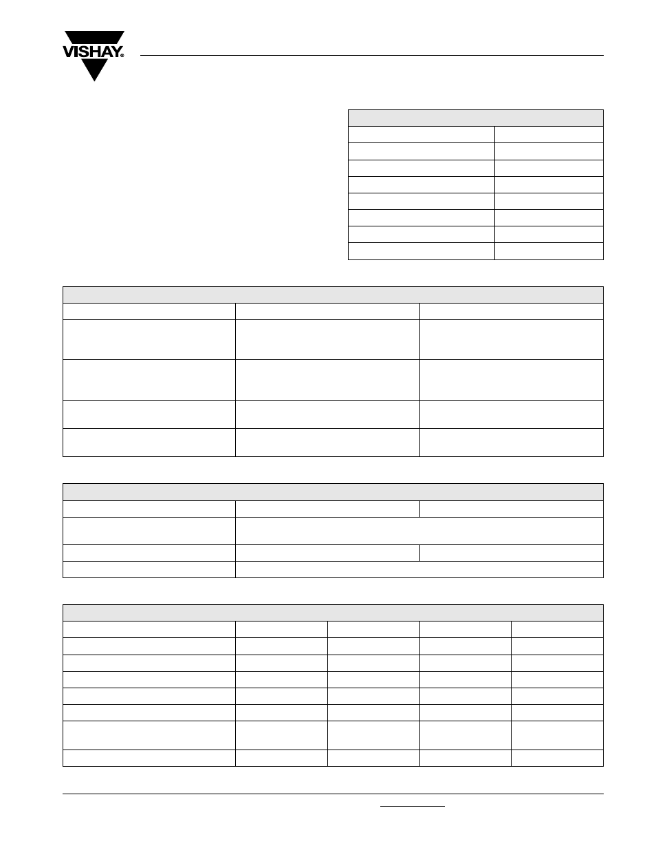
MECHANICAL SPECIFICATIONS
Mechanical Protection
Insulated case
Substrate Alumina
Resistive Element
Cermet
Connections
Tinned copper alloy
ENVIRONMENTAL SPECIFICATIONS
Temperature Range
- 55 °C to + 125 °C
Climatic Category
55/125/56
ELECTRICAL SPECIFICATIONS
Resistance Range
0.24
Ω to 1 MΩ E24 series
Standard Resistance Tolerances
± 1 %, ± 2 %, ± 5 %, ± 10 %
Power Rating:
Chassis Mounted
5 W to 50 W
Unmounted
2 W to 5.5 W
Temperature Coeffi cient
± 150 ppm/°C (R > 1
Ω)
Insulation Resistance
10
6
M
Ω
Total Inductance
≤ 0.1 µH
PERFORMANCE
TESTS
CONDITIONS
TYPICAL DRIFTS
Momentary Overload
NF EN 140 000 CEI 115_1
2
P
r
/5 s
U
s
< 2 UL
< ± (0.25 % + 0.05
Ω)
Rapid Temperature Change
NF EN 140 000 125 °C CEI 68215 Test Na
5 cycles
- 55 °C to + 125 °C
< ± (0.25 % + 0.05
Ω)
Load Life
NF EN 140 000 CEI 115_1
1000 h
P
r
at + 25 °C
< ± (0.5 % + 0.05
Ω)
Humidity (Steady State)
56 days RH 95 %
MIL STD 202 Method 103 B and C
< ± (0.5 % + 0.05
Ω)
RESISTANCE VALUE IN RELATION TO TOLERANCE AND TCR
Resistance Value
< 1
Ω
> 1
Ω
Standard
Tolerances
± 5 %
± 10 %
Standard TCR
± 250 ppm/°C
± 150 ppm/°C
Tolerance on Request
± 1 % to ± 2 %
SPECIAL FEATURES
MODEL
RCH 5
RCH 10
RCH 25
RCH 50
Power Rating-Chassis Mounted
5 W
10 W
25 W
50 W
Power Rating-Unmounted
2 W
2.5 W
4 W
5.5 W
Thermal Resistance R
TH
(j-c)
4.8 °C/W
3.2 °C/W
1.4 °C/W
0.8 °C/W
Limiting Element Voltage (V
RMS
)
160 V
250 V
550 V
1285 V
Max. Overload Voltage (V
RMS
)
320 V
500 V
1100 V
2500 V
Dielectric Strength (V
RMS
) 50 Hz, 1 Min
MIL STD 202 Method 301 10 mA Max.
2000 V
2000 V
3500 V
3500 V
Critical Resistance
5120
Ω
6250
Ω
12 100
Ω
33 024
Ω