C&H Technology PS51789 User Manual
Page 4
PS51789
Intellimod™ Module
Dual-In-Line Intelligent Power Factor Correction Module
30 Amperes/600 Volts
3
03/10 Rev. 0
Powerex, Inc., 173 Pavilion Lane, Youngwood, Pennsylvania 15697 (724) 925-7272 www.pwrx.com
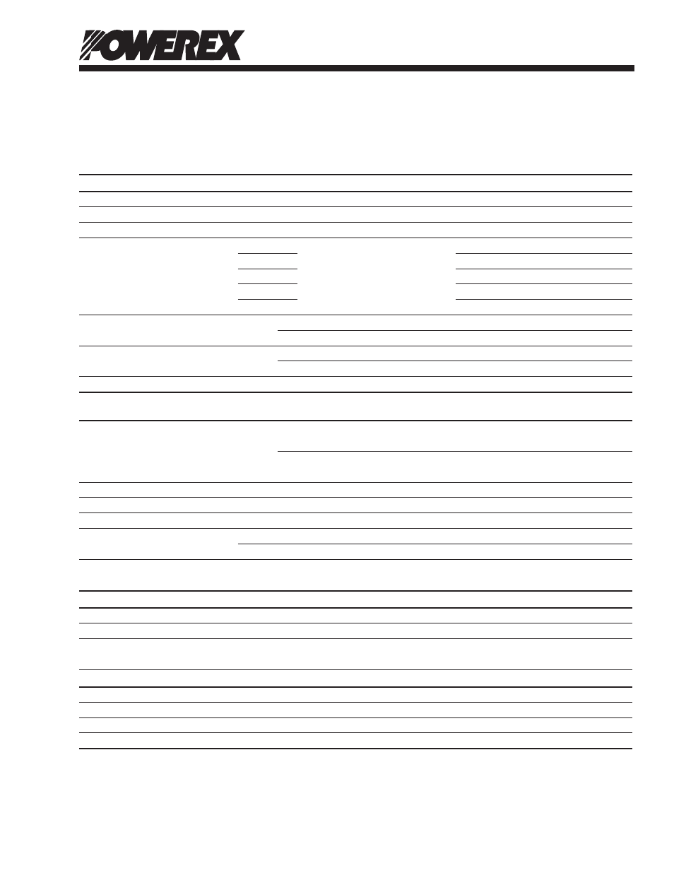
Electrical and Mechanical Characteristics, T
j
= 25°C unless otherwise specified
Characteristics
Symbol
Test Conditions
Min.
Typ.
Max.
Units
Collector-Emitter Saturation Voltage
V
CE(sat)
V
D
= 15V, V
IN
= 5V, I
C
= 50A
—
2.0
2.6
Volts
H-Diode Forward Voltage*
V
F(H)
I
F
= 50A, Applied Between R-P, S-P
—
2.1
2.7
Volts
L-Diode Forward Voltage*
V
F(L)
I
F
= 50A, Applied Between N2-R, N2-S
—
1.1
1.4
Volts
Inductive Load Switching Times
t
on
—
0.25
0.35
µs
t
C(on)
V
CC
= 300V, V
D
= 15V,
—
0.14
0.23
µs
t
off
I
C
= 40A, T
j
= 125°C,
—
0.40
0.65
µs
t
off
Inductive Load, V
IN
= 0 ⇔ 5V
—
0.18
0.35
µs
t
rr
—
0.11
—
µs
Collector-Emitter Cutoff Current
I
CES
V
CE
= 600V, T
j
= 25°C
—
—
1.0
mA
V
CE
= 600V, T
j
= 125°C
—
—
10
mA
Reverse Current
I
R
V
R
= 600V, T
j
= 25°C
—
—
1.0
mA
V
R
= 600V, T
j
= 125°C
—
—
10
mA
Diode Recovery Current
Irr
V
CC
= 300V, V
D
= 15V, I
C
= 40A
—
14
—
Amperes
Control Sector
Circuit Current
I
D
Applied Between V
D
-GND,
—
0.8
3.0
mA
V
D
= 15V, V
IN
= 5V
Applied Between V
D
-GND,
—
0.7
3.0
mA
V
D
= 15V, V
IN
= 0V
Input Current
I
IN
V
D
= 15V, V
IN
= 5V
—
0.3
0.45
mA
ON Threshold Voltage
V
th(on)
Applied Between V
IN
-GND
—
2.1
2.6
Volts
OFF Threshold Voltage
V
th(off)
Applied Between V
IN
-GND
0.8
1.3
—
Volts
Supply Circuit Undervoltage
UV
Dt
Trip Level, T
j
≤ 125°C
10.3
—
12.5
Volts
Protection
UV
Dr
Reset Level, T
j
≤ 125°C
10.8
—
13.0
Volts
Thermal Characteristics, T
j
= 25°C unless otherwise specified
Characteristic
Symbol
Condition
Min.
Typ.
Max.
Units
Thermal Resistance Junction to Case R
th(j-C)Q
IGBT Part (Per 1 Chip)
—
—
0.68
°C/Watt
Thermal Resistance Junction to Case R
th(j-C)D
FWDi Part (Per 1 Chip)
—
—
0.90 °C/Watt
Recommended Conditions for Use
Characteristic
Symbol
Condition
Min.
Typ.
Max.
Units
Input Supply Voltage
V
i
Applied between S-R
90
—
264
V
rms
Control Supply Voltage
V
D
Applied between V
D
-GND
13.5
15.0
16.5
Volts
Control Supply Variation
∆V
D
-1
—
1
V/µs
PWM Input Frequency
f
PWM
T
C
≤ 100°C, T
j
≤ 125°C
—
20
—
kHz
*H-Diode and L-Diode corresponds to Diode1, Diode 2 and Diode 3, Diode 4 in the Application circuit.