St083spbf series, Vishay high power products, Inverter grade thyristors (stud version), 85 a – C&H Technology ST083SPbF Series User Manual
Page 4: Switching, Blocking, Triggering, Thermal and mechanical specifications
Document Number: 94334
For technical questions, contact: [email protected]
www.vishay.com
Revision: 29-Apr-08
3
ST083SPbF Series
Inverter Grade Thyristors
(Stud Version), 85 A
Vishay High Power Products
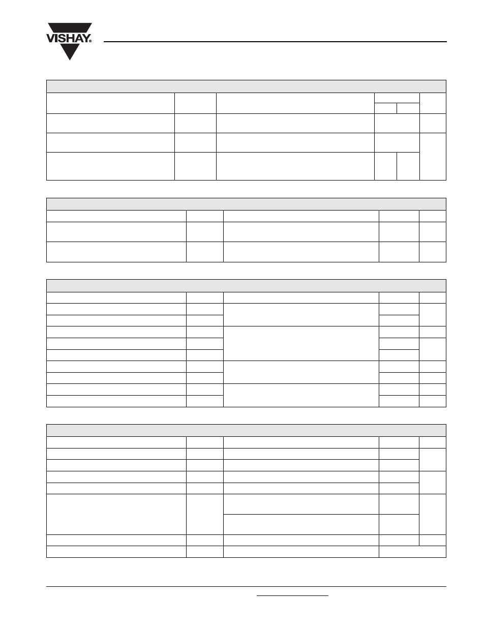
SWITCHING
PARAMETER SYMBOL
TEST
CONDITIONS
VALUES
UNITS
MIN.
MAX.
Maximum non-repetitive rate of rise
of turned on current
dI/dt
T
J
= T
J
max., V
DRM
= Rated V
DRM
, I
TM
= 2 x dI/dt
1000
A/µs
Typical delay time
t
d
T
J
= 25 °C, V
DM
= Rated V
DM
, I
TM
= 50 A DC, t
p
= 1 µs
Resistive load, gate pulse: 10 V, 5
Ω source
0.80
µs
Maximum turn-off time
t
q
T
J
= T
J
maximum, I
TM
= 100 A,
commutating dI/dt = 10 A/µs
V
R
= 50 V, t
p
= 200 µs, dV/dt = 200 V/µs
10
20
BLOCKING
PARAMETER SYMBOL
TEST
CONDITIONS
VALUES
UNITS
Maximum critical rate of rise of off-state voltage
dV/dt
T
J
= T
J
maximum, linear to 80 % V
DRM
, higher value
available on request
500
V/µs
Maximum peak reverse and
off-state leakage current
I
RRM
,
I
DRM
T
J
= T
J
maximum, rated V
DRM
/V
RRM
applied
30
mA
TRIGGERING
PARAMETER SYMBOL
TEST
CONDITIONS
VALUES
UNITS
Maximum peak gate power
P
GM
T
J
= T
J
maximum, f = 50 Hz, d% = 50
40
W
Maximum average gate power
P
G(AV)
5
Maximum peak positive gate current
I
GM
T
J
= T
J
maximum, t
p
≤ 5 ms
5
A
Maximum peak positive gate voltage
+ V
GM
20
V
Maximum peak negative gate voltage
- V
GM
5
Maximum DC gate currrent required to trigger
I
GT
T
J
= 25 °C, V
A
= 12 V, R
a
= 6
Ω
200
mA
Maximum DC gate voltage required to trigger
V
GT
3
V
Maximum DC gate current not to trigger
I
GD
T
J
= T
J
maximum, rated V
DRM
/V
RRM
applied
20
mA
Maximum DC gate voltage not to trigger
V
GD
0.25
V
THERMAL AND MECHANICAL SPECIFICATIONS
PARAMETER SYMBOL
TEST
CONDITIONS
VALUES
UNITS
Maximum junction operating temperature range
T
J
- 40 to 125
°C
Maximum storage temperature range
T
Stg
- 40 to 150
Maximum thermal resistance, junction to case
R
thJC
DC operation
0.195
K/W
Maximum thermal resistance, case to heatsink
R
thCS
Mounting surface, smooth, flat and greased
0.08
Mounting torque, ± 10 %
Non-lubricated threads
15.5
(137)
N · m
(lbf · in)
Lubricated threads
14
(120)
Approximate weight
130
g
Case style
See dimensions - link at the end of datasheet
TO-209AC (TO-94)