Vsk.56..pbf/vsk.71..pbf series, Vishay high power products, Standard diodes, 60/80 a (add-a-pak – C&H Technology VSK.56..PbF-VSK.71..PbF Series User Manual
Page 6: Generation 5 power modules)
Document Number: 94358
For technical questions, contact: [email protected]
www.vishay.com
Revision: 04-Jul-08
5
VSK.56..PbF/VSK.71..PbF Series
Standard Diodes, 60/80 A
(ADD-A-PAK
TM
Generation 5 Power Modules)
Vishay High Power Products
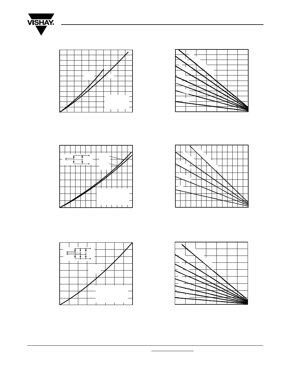
Fig. 7 - Forward Power Loss Characteristics
Fig. 8 - Forward Power Loss Characteristics
Fig. 9 - Forward Power Loss Characteristics
0
100
120
20
40
60
80
Maximum Total Forward
Power Loss (W)
Total RMS Output Current (A)
20
40
60
80
100
0
180°
(Sine)
DC
VSK.56.. Series
Per junction
T
J
= 150 °C
0
100
120
40
60
20
80
Maximum Total Forward
Power Loss (W)
Maximum Allowable Ambient
Temperature (°C)
20
40
60
80
100
140
120
0
0.7 K/
W
R
thSA
= 0.5 K/
W
- Δ
R
1.0 K/
W
1.5 K/
W
7.0 K/W
3.0 K/
W
2.0 K/
W
0
350
400
450
300
250
200
150
100
50
Maximum Total Power Loss (W)
Total Output Current (A)
20
40
60
80
100
140
120
0
180°
(Sine)
180°
(Rect)
2 x VSK.56.. Series
Single phase bridge
Connected
T
J
= 150 °C
+
-
~
0
300
350
400
450
250
200
150
100
50
Maximum Total Power Loss (W)
20
40
60
80
100
120
140
0
Maximum Allowable Ambient
Temperature (°C)
R
thSA
= 0.1 K/
W
- Δ
R
0.2 K/
W
0.3 K/
W
0.5 K/
W
1.0 K/
W
0
350
400
450
300
250
200
150
100
50
Maximum Total Power Loss (W)
Total Output Current (A)
20
40
60
80
120
100
160
140
0
120°
(Rect)
3 x VSK.56.. Series
Three phase bridge
Connected
T
J
= 150 °C
+
-
~
0
100
150
200
250
300
350
400
450
50
Maximum Total Power Loss (W)
Maximum Allowable Ambient
Temperature (°C)
20
40
60
80
100
120
140
0
0.3 K/
W
0.4 K/
W
0.5 K/
W
0.7 K/
W
1.0 K/
W
1.5 K/W
3.0 K/W
R
thSA
= 0.1 K/
W
- Δ
R