Z300, Vishay draloric, Axial cemented wirewound resistors – C&H Technology Z300 User Manual
Page 4: Dimensions, Dimensions zdv0411
www.vishay.com
For technical questions, contact: [email protected]
Document Number: 21007
108
Revision: 17-Apr-07
Z300
Vishay Draloric
Axial Cemented Wirewound Resistors
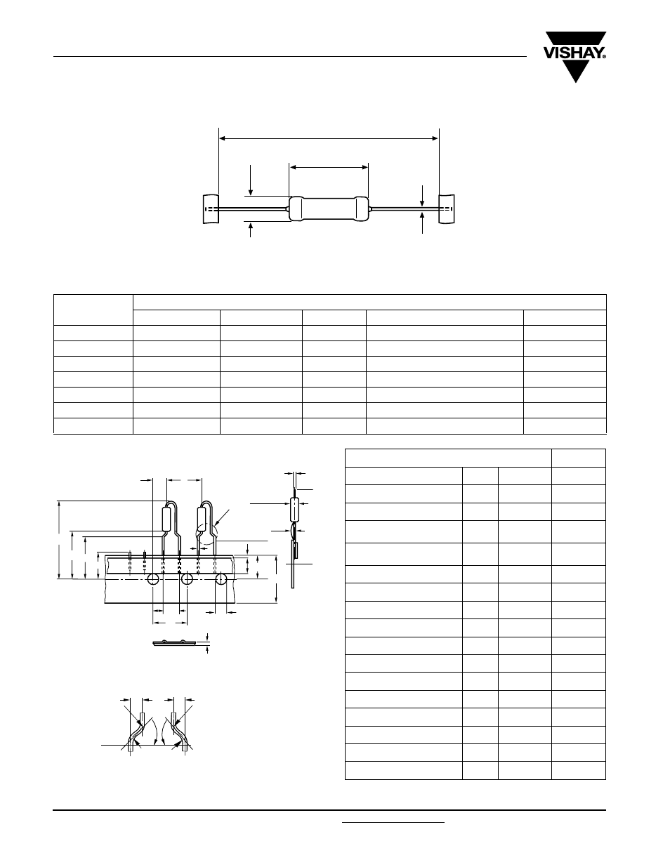
DIMENSIONS
For packaging dimensions see appropriate catalog or web page.
DIMENSIONS ZDV0411
1) Test over 10 holes - 9 intervals P
0
12 × 9 = 114.3 ± 0.5
2) Parallelism, < 0.5 mm
3) Thickness of carrier tape: 0.55 mm ± 0.1
B
A
G
C
MODEL
DIMENSIONS in millimeters [inches]
A
max
B
max
C
max
G
Weight (g)
Z301
8.5 [0.355]
3 [0.118]
0.7 [0.027]
53 ± 1 [2.087 ± 0.039]
0.5
ZDA0411
11 [0.433]
4 [0.157]
0.7 [0.027]
53 ± 1 [2.087 ± 0.039
0.8
Z302
13 [0.512]
4.8 [0.189]
0.8 [0.031]
53 ± 1 [2.087 ± 0.039]
1.1
Z303
15.8 [0.622]
5.5 [0.217]
0.8 [0.031]
53 ± 1 [2.087 ± 0.039]
1.4
Z305
22.3 [0.878]
8.7 [0.343]
0.8 [0.031]
83 ± 1 [3.268 ± 0.039]
3.7
Z306
32.3 [1.272]
8.7 [0.343]
0.8 [0.031]
83 ± 1 [3.268 ± 0.039]
5
Z307
49.8 [1.961
9 [0.354]
0.8 [0.031]
120 ± 2 [4.724 ± 0.079]
7
F
P
W
1 max.
t
“Z”
d
H
1
L
H
H
0
P
2
Δh
1
W
2
W
0
W
1
P
1
P
0
D
0
Ø 4 max.
R
R
R
R
d
1
d
1
/ d
2
= 35 ... 45°
a
1
/ a
2
= < 1.25
d
2
a
1
a
2
DIMENSIONS (in millimeters)
TOL.
Lead Ø
d
0.6
Pitch of components
P
12.7
± 1.0
Pitch of sprocket holes
1)
P
0
12.7
± 0.3
Distance between hole
center and resistor center
P
1
3.85
± 0.7
Distance between hole
center and lead center
P
2
6.35
± 0.7
Lead spacing
F
5
+ 0.6, - 0.1
Angle of Insertion
Δh1
2 max.
-
Width of carrier tape
W
18.0
+ 1, - 0.5
Width of adhesive tape
W
0
12.0
± 0.5
Position of holes
W
1
9
+ 0.75, - 0.5
Position of adhesive tape
W
2
0.5
+ 0, - 0.5
Body to hole center
H
16.0
± 0.5
Lead crimp to hole center
2)
H
0
19.5
± 1.0
Hole Ø
D
0
4.0
± 0.2
Thickness of tape
3)
t
0.9 max.
-
Height of cutting
L
11 max.
-
Height of insertion
H
1
32.3 max.
-
Area “Z”
For body dimensions, see dimensions table above, model ZDA0411.