Hl, nhl flat and hlm, nhlm, Vishay dale – C&H Technology NHLM User Manual
Page 3
HL, NHL FLAT and HLM, NHLM
Vishay Dale
Wirewound Resistors,
Industrial Power, Flat (HL), Miniature Flat (HLM)
www.vishay.com
For technical questions, contact: [email protected]
Document Number: 30209
74
Revision: 13-Jul-07
POWER RATING
Vishay HL flat and HLM resistor wattage ratings are
based on mounting horizontally to 10" x 10" x 0.04"
[254.0 mm x 254.0 mm x 1.02 mm] steel plate in 25 °C
ambient with no air flow.
EXCLUSIVE BRACKET DESIGN
Mounting strap fits snugly through resistor core and is
bound against unit by two eccentric spacers. The bracket
eliminates expensive cements and improves heat transfer
and power handling capabilities.
MATERIAL SPECIFICATIONS
Element: Copper-nickel alloy of nickel-chrome alloy,
depending on resistance value
Core: Ceramic, steatite
Coating: Special high temperature silicone
Standard Terminals: Model “Z” terminals are tinned steel
Terminal Bands: Steel
Part Marking: DALE, model, wattage, value, tolerance, date
code
NHL, NHLM NON-INDUCTIVE
Models of equivalent physical and electrical specifications
are available with non-inductive (Aryton-Perry) winding.
They are identified by adding the letter N to the front of the
HL and HLM type designation (NHLM020, for example). For
NHL and NHLM models maximum resistance values are
lower, see STANDARD ELECTRICAL SPECIFICATIONS
table.
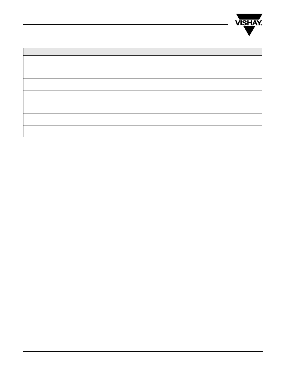
TECHNICAL SPECIFICATIONS
PARAMETER
UNIT
HL, HLM RESISTOR CHARACTERISTICS
Temperature Coefficient
ppm/°C
± 90 for 0.1
Ω to 0.99 Ω; ± 50 for 1 Ω to 9.9 Ω; ± 30 for 10 Ω and above
Dielectric Withstanding Voltage
V
AC
1000, from terminal to mounting hardware
Short Time Overload
-
10 x rated power for 5 s
Maximum Working Voltage
V
(
P x R)
1/2
Insulation Resistance
Ω
1000 M
Ω minimum dry, 100 MΩ minimum after moisture test
Operating Temperature Range
°C
- 55 to + 350