St103sp series, Vishay high power products, Inverter grade thyristors (stud version), 105 a – C&H Technology ST103SP Series User Manual
Page 8
Document Number: 94365
For technical questions, contact: [email protected]
www.vishay.com
Revision: 29-Apr-08
7
ST103SP Series
Inverter Grade Thyristors
(Stud Version), 105 A
Vishay High Power Products
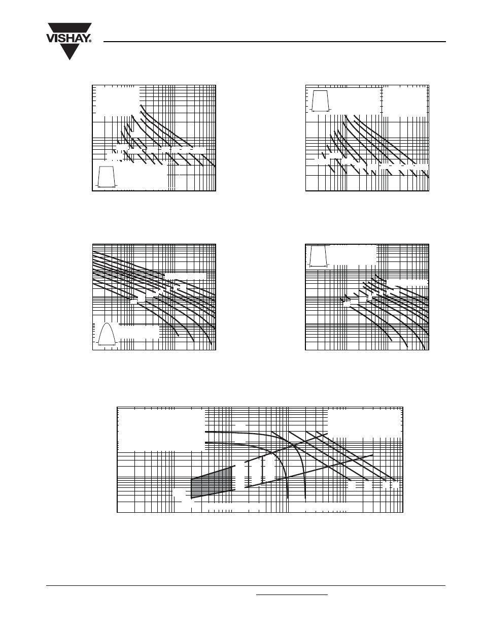
Fig. 13 - Frequency Characteristics
Fig. 14 - Maximum On-State Energy Power Loss Characteristics
Fig. 15 - Gate Characteristics
10
100
1000
10 000
100
1000
10 000
Pulse Basewidth (µs)
Peak On-State Current (A)
Snubber circuit
R
s
= 22
Ω
C
s
= 0.15 µF
V
D
= 80 % V
DRM
ST103S Series
Trapezoidal pulse
T
C
= 60 °C
dI/dt = 100 A/µs
t
p
50 Hz
100
200
400
1000
1500
2500
5000
10 000
10
100
1000
10 000
Pulse Basewidth (µs)
Peak On-State Current (A)
100
1000
10 000
50 Hz
400
2500
100
1500
200
5000
10 000
1000
Snubber circuit
R
s
= 22
Ω
C
s
= 0.15 µF
V
D
= 80 % V
DRM
ST103S Series
Trapezoidal pulse
T
C
= 85 °C
dI/dt = 100 A/µs
t
p
Pulse Basewidth (µs)
Peak On-State Current (A)
10
100
1000
10 000
10
100
1000
10 000
t
p
ST103S Series
Sinusoidal pulse
100 000
0.1
0.2
0.5
2 3
1
5 10
20 joules per pulse
Pulse Basewidth (µs)
Peak On-State Current (A)
10
100
1000
10 000
10
100
1000
10 000
100 000
0.1
0.2
0.5
2 3
1
5 10
20 joules per pulse
t
p
ST103S Series
Rectangular pulse
dI/dt = 50 A/µs
0.1
1
10
100
0.001
Instantaneous Gate Current (A)
Instantaneous Gate Voltage (V)
0.01
0.1
1
10
100
V
GD
I
GD
(1)
(2)
(3)
Device: ST103S Series
(4)
Frequency limited by P
G(AV)
T
J
= 25 °C
T
J
= 40 °C
T
J
= 125 °C
(a)
(b)
Rectangular gate pulse
a) Recommended load line for
rated di/dt: 20 V, 10
Ω; t
r
≤ 1 µs
b) Recommended load line for
≤ 30 % rated di/dt: 10 V, 10 Ω
t
r
≤ 1 µs
(1) P
GM
= 10 W, t
p
= 20 ms
(2) P
GM
= 20 W, t
p
= 10 ms
(3) P
GM
= 40 W, t
p
= 5 ms
(4) P
GM
= 60 W, t
p
= 3.3 ms