Vishay semiconductors – C&H Technology VS-GB90SA120U User Manual
Page 7
VS-GB90SA120U
www.vishay.com
Vishay Semiconductors
Revision:02-Aug-12
6
Document Number: 94725
For technical questions within your region:
,
,
THIS DOCUMENT IS SUBJECT TO CHANGE WITHOUT NOTICE. THE PRODUCTS DESCRIBED HEREIN AND THIS DOCUMENT
ARE SUBJECT TO SPECIFIC DISCLAIMERS, SET FORTH AT
www.vishay.com/doc?91000
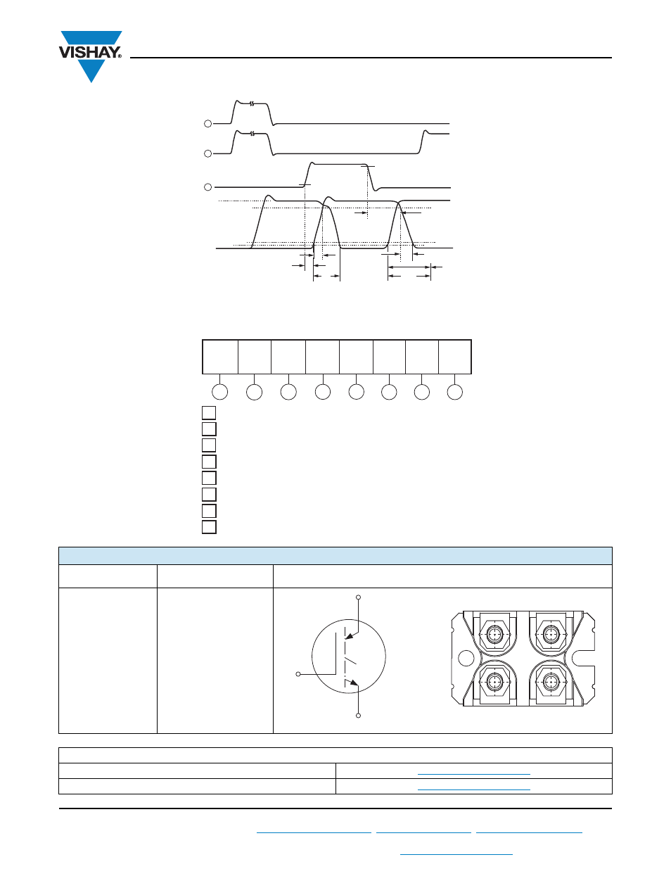
Fig. 14b - Switching Loss Waveforms Test Circuit
ORDERING INFORMATION TABLE
CIRCUIT CONFIGURATION
CIRCUIT
CIRCUIT
CONFIGURATION CODE
CIRCUIT DRAWING
Single switch, no
antiparallel diode
S
LINKS TO RELATED DOCUMENTS
Dimensions
www.vishay.com/doc?95423
Packaging information
www.vishay.com/doc?95425
t = 5 µs
t
d(on)
t
f
t
r
90 %
t
d(off)
10 %
90 %
10 %
5 %
V
C
I
C
E
on
E
off
E
ts
= (E
on
+ E
off
)
1
2
3
1
-
Insulated Gate Bipolar Transistor (IGBT)
-
Vishay Semiconductors product
2
-
B = IGBT Generation 5
3
-
Current rating (90 = 90 A)
4
-
Circuit configuration (S = Single switch without antiparallel diode)
5
-
Package indicator (A = SOT-227)
6
-
Voltage rating (120 = 1200 V)
8
7
-
Speed/type (U = Ultrafast IGBT)
Device code
5
1
3
2
4
6
7
8
G
VS-
B
90
S
A
120
U
3 (C)
2 (G)
1, 4 (E)
1
4
3
2
Lead Assignment