Vsk.71, .91..pbf series, Vishay high power products, Thyristor/diode and thyristor/thyristor (add-a-pak – C&H Technology VSK.91..PbF Series User Manual
Page 7
www.vishay.com
For technical questions, contact: [email protected]
Document Number: 94421
6
Revision: 24-Apr-08
VSK.71, .91..PbF Series
Vishay High Power Products
Thyristor/Diode and Thyristor/Thyristor
(ADD-A-PAK
TM
Generation 5 Power Modules),
75/95 A
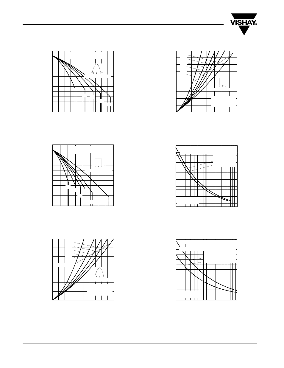
Fig. 10 - Current Ratings Characteristics
Fig. 11 - Current Ratings Characteristics
Fig. 12 - On-State Power Loss Characteristics
Fig. 13 - On-State Power Loss Characteristics
Fig. 14 - Maximum Non-Repetitive Surge Current
Fig. 15 - Maximum Non-Repetitive Surge Current
70
80
90
100
110
120
130
0
20
40
60
80
100
30°
60°
90°
120°
180°
Average On-state Current (A)
M
a
x
im
u
m
A
llo
w
a
b
le C
a
se
T
e
m
p
e
rat
u
re (
°C
)
Cond uc tion Angle
VSK.91.. Series
R (DC) = 0.27 K/ W
thJC
70
80
90
100
110
120
130
0
20
40
60
80
100 120 140 160
DC
30°
60°
90°
120°
180°
Average On-state Current (A)
M
a
x
im
u
m
A
llo
wa
bl
e
C
a
se
T
e
m
p
e
rat
u
re (
°C
)
Conduc tion Period
VSK.91.. Series
R (DC) = 0.27 K/ W
thJC
0
20
40
60
80
100
120
140
0
20
40
60
80
100
RMS Limit
Conduc tio n Angle
M
a
x
imu
m
A
v
e
ra
g
e
O
n
-s
ta
te
P
o
w
e
r
L
o
ss
(
W
)
Average On-state Current (A)
180°
120°
90°
60°
30°
VSK.91.. Series
Per Junc tion
T = 125°C
J
0
20
40
60
80
100
120
140
160
180
0
20
40
60
80
100 120 140 160
DC
180°
120°
90°
60°
30°
RMS Limit
Conduc tion Period
Ma
x
imu
m A
v
e
ra
g
e
O
n
-s
ta
te
P
o
w
e
r L
o
ss
(
W
)
Average On-state Current (A)
VSK.91.. Series
Per Junc tion
T = 125°C
J
700
800
900
1000
1100
1200
1300
1400
1500
1600
1
10
100
Numb er Of Eq ua l Amp litud e Half Cyc le Current Pulses (N)
P
e
a
k
H
a
lf
S
in
e
W
a
v
e
O
n
-s
ta
te
C
u
rr
e
n
t
(A
)
Initial T = 125°C
@ 60 Hz 0.0083 s
@ 50 Hz 0.0100 s
J
At Any Rated Loa d Condition And With
Rated V Applied Following Surg e.
RRM
VSK.91.. Series
Per Junction
600
800
1000
1200
1400
1600
1800
0.01
0.1
1
P
e
a
k
H
a
lf
S
in
e
W
a
v
e
O
n
-s
ta
te
C
u
rr
e
n
t (
A
)
Pulse Train Duration (s)
Versus Pulse Train Duration. Control
Initial T = 125°C
No Voltage Reap p lied
Ra ted V Reap p lied
RRM
J
Of Cond uc tion Ma y Not Be Ma intained .
Ma ximum Non Repetitive Surg e Current
VSK.91.. Series
Per Junction