Vsk.71, .91..pbf series, Vishay high power products, Thyristor/diode and thyristor/thyristor (add-a-pak – C&H Technology VSK.91..PbF Series User Manual
Page 6
Document Number: 94421
For technical questions, contact: [email protected]
www.vishay.com
Revision: 24-Apr-08
5
VSK.71, .91..PbF Series
Thyristor/Diode and Thyristor/Thyristor
(ADD-A-PAK
TM
Generation 5 Power Modules),
75/95 A
Vishay High Power Products
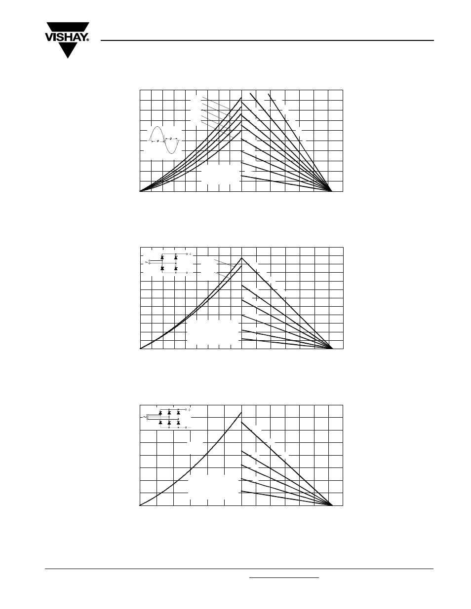
Fig. 7 - On-State Power Loss Characteristics
Fig. 8 - On-State Power Loss Characteristics
Fig. 9 - On-State Power Loss Characteristics
0
20
40
60
80
100
120
140
Maximum Allowable Ambient Temperature (°C)
R
=
0
.1
K
/ W
-
D
e
lta
R
th
S
A
3 K/W
1.5 K
/ W
1 K/
W
0.7
K/ W
0.5
K/
W
0.4
K/
W
0.3
K
/ W
0.2
K/
W
0
50
100
150
200
250
0
20
40
60
80 100 120 140 160 180
180°
120°
90°
60°
30°
Total RMS Outp ut Current (A)
M
a
x
im
u
m
T
o
ta
l O
n
-s
ta
te
P
o
w
e
r L
o
ss
(
W
)
Conduction Angle
VSK.71.. Series
Per Mod ule
T = 125°C
J
0
20
40
60
80
100
120
140
Maximum Allowable Ambient Temperature (°C)
R
=
0.1
K/
W
-
D
elt
a
R
th
SA
0.3
K/ W
0.5
K/W
1 K/ W
2 K/ W
0.2
K/ W
0
100
200
300
400
500
600
0
20
40
60
80 100 120 140 160 180
Total Output Current (A)
Ma
x
imu
m
To
ta
l
P
o
w
e
r L
o
ss
(
W
)
180°
(Sine)
180°
(Rec t)
2 x VSK.71.. Series
Single Phase Bridge
Connec ted
T = 125°C
J
0
20
40
60
80
100
120
140
Maximum Allowable Ambient Temperature (°C)
1 K/ W
0.5
K/ W
0.3
K/ W
R
=
0.1
K/
W
- D
e
lta
R
0.2
K/ W
th
SA
0
100
200
300
400
500
600
700
800
0
40
80
120
160
200
240
Total Output Current (A)
Ma
x
imu
m
T
o
ta
l P
o
w
e
r L
o
ss
(
W
)
120°
(Rec t)
3 x VSK.71.. Series
Three Pha se Brid ge
Connec ted
T = 125°C
J