Vishay high power products – C&H Technology VSK.250PbF Series User Manual
Page 8
Document Number: 94417
For technical questions, contact:
www.vishay.com
Revision: 08-Oct-09
7
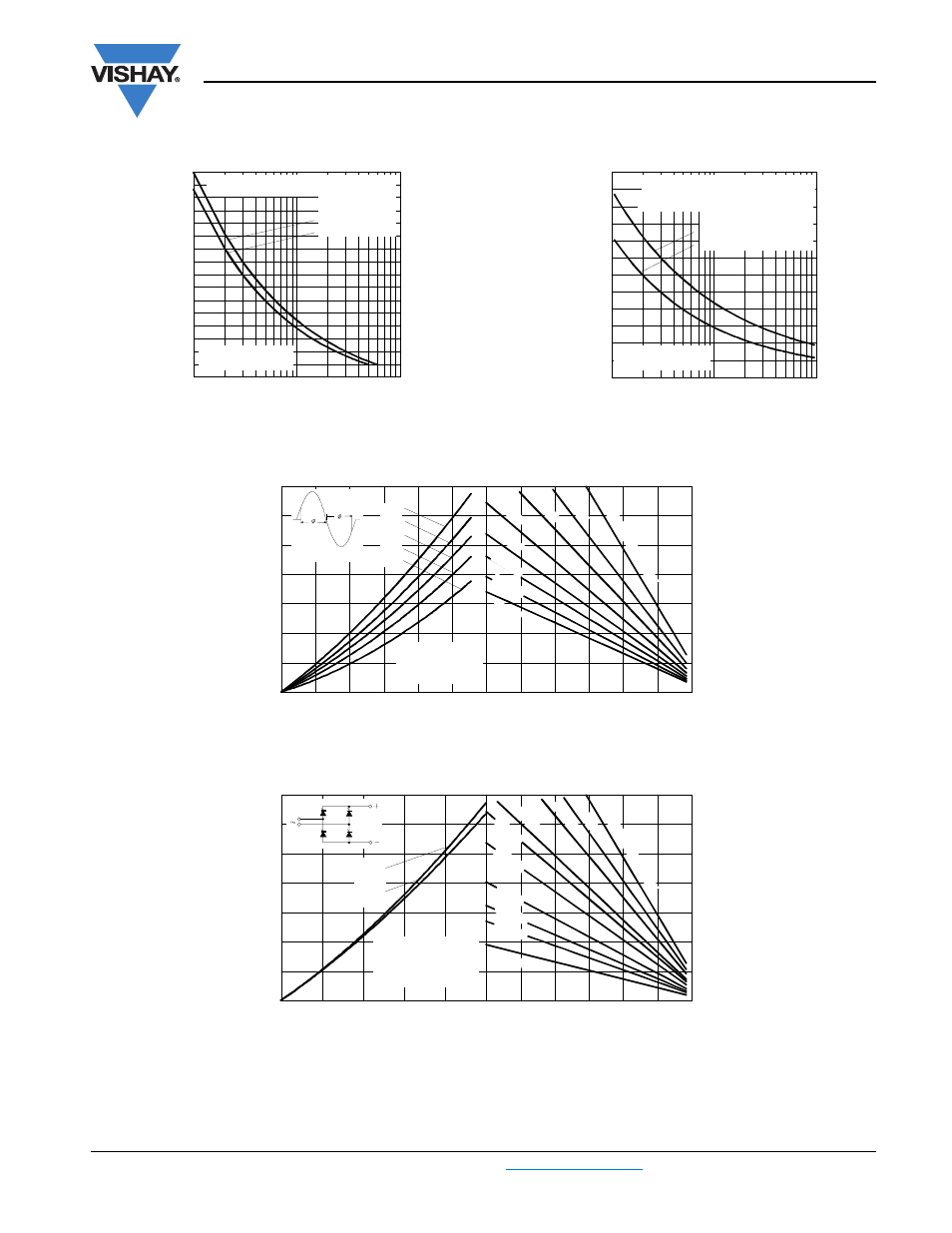
VSK.170PbF, VSK.250PbF Series
SCR/SCR and SCR/Diode
(MAGN-A-PAK Power Modules), 170 A/250 A
Vishay High Power Products
Fig. 14 - Maximum Non-Repetitive Surge Current
Fig. 15 - Maximum Non-Repetitive Surge Current
Fig. 16 - On-State Power Loss Characteristics
Fig. 17 - On-State Power Loss Characteristics
3500
4000
4500
5000
5500
6000
6500
7000
7500
1
10
100
Number Of Equal Amplitude Half Cycle Current Pulses (N)
Pe
a
k
Ha
lf
S
ine
W
a
v
e
O
n
-s
tate
C
u
rr
e
n
t (
A
)
VSK.250.. Series
Per Junction
At Any Rated Load Condition And With
Rated V
RRM
Applied Following Surge.
Initial T = 130°C
@ 60 Hz 0.0083 s
@ 50 Hz 0.0100 s
J
3000
4000
5000
6000
7000
8000
9000
0.01
0.1
1
P
e
a
k
Ha
lf
S
in
e
W
a
v
e
On
-s
ta
te
Cu
rr
e
n
t (
A
)
Pulse Train Duration (s)
Maximum Non Repetitive Surge Curren t
Versus Pulse Train Duration. Control
Of Conduction May Not Be Maintained .
VSK.250.. Series
Per Junction
Initial T
J
= 130°C
No Voltage Reapplied
Rated V
RRM
Reapplied
0
20
40
60
80
100
120
Maximum Allowable Ambient Temperature (°C)
0.3
K/ W
0.25
K/ W
0.2
0
K/W
0.1
6
K/ W
0.1
2
K/
W
0.0
8
K/
W
0.0
5
K
/ W
R
=
0
.0
2
K
/ W
-
D
e
lta
R
th
SA
0
100
200
300
400
500
600
700
0
100
200
300
400
500
600
180°
120°
90°
60°
30°
Max
im
u
m
T
o
ta
l O
n
-s
ta
te
P
o
w
e
r L
o
s
s (
W
)
Conduction angle
Total RMS Output Current (A)
VSK.250.. Series
Per Module
T
J
= 130°C
0
20
40
60
80
100
120
Maximum Allowable Ambient Temperature (°C)
R
=
0
.0
1
K
/ W
-
D
e
lta
R
th
SA
0.02
K/
W
0.0
3
K
/ W
0.0
4
K/
W
0.0
5
K/
W
0.0
6 K
/ W
0.1
K/ W
0.12
K/ W
0.16
K/ W
0.3 K/ W
0
200
400
600
800
1000
1200
1400
0
100
200
300
400
500
Ma
x
imu
m
T
o
ta
l P
o
w
e
r L
o
ss (
W
)
Total Output Current (A)
180°
(Sine)
180°
(Rect)
2 x VSK.250.. Series
Single Phase Bridge
Connected
T
J
= 130°C