Vskd600.. series, Vishay high power products, Standard diodes, 600 a (super magn-a-pak – C&H Technology VSKD600.. Series User Manual
Page 4: Power modules), Conduction
Document Number: 93583
For technical questions, contact: [email protected]
www.vishay.com
Revision: 11-Aug-08
3
VSKD600.. Series
Standard Diodes, 600 A
(SUPER MAGN-A-PAK
TM
Power Modules)
Vishay High Power Products
Note
• The table above shows the increment of thermal resistance R
thJC
when devices operate at different conduction angles than DC
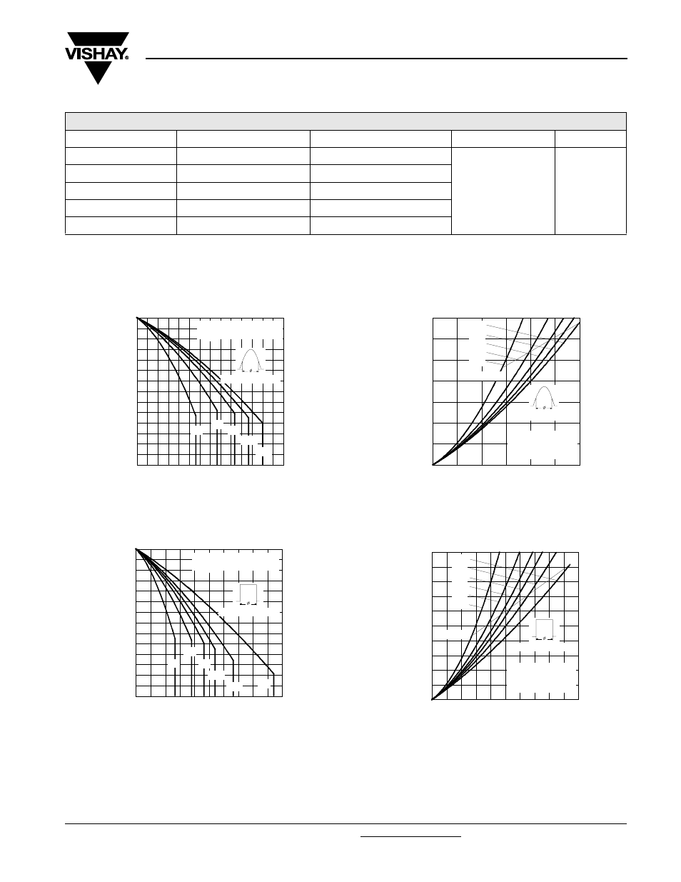
Fig. 1 - Current Ratings Characteristics
Fig. 2 - Current Ratings Characteristics
Fig. 3 - Forward Power Loss Characteristics
Fig. 4 - Forward Power Loss Characteristics
ΔR
thJC
CONDUCTION
CONDUCTION ANGLE
SINUSOIDAL CONDUCTION
RECTANGULAR CONDUCTION
TEST CONDITIONS
UNITS
180°
0.009
0.006
T
J
= T
J
maximum
K/W
120°
0.011
0.011
90°
0.014
0.015
60°
0.021
0.022
30°
0.037
0.038
80
90
100
110
120
130
140
150
0
100
200
300
400
500
600
700
30°
60°
90°
120°
180°
M
a
x
imu
m
Al
lo
w
a
bl
e
C
a
se
T
e
mp
e
ra
tu
re
(°
C
)
Conduction Angle
Average Forward Current (A)
VSKD600.. Series
R (DC) = 0.065 K/W
thJC
80
90
100
110
120
130
140
150
0
200
400
600
800
1000
DC
30°
60°
90°
120°
180°
M
a
x
im
u
m A
llo
w
a
b
le C
a
s
e
T
e
m
p
er
a
tu
re (
°C
)
Conduction Period
Average Forward Current (A)
VSKD600.. Series
R (DC) = 0.065 K/W
thJC
0
100
200
300
400
500
600
700
0
100
200
300
400
500
600
Average Forward Current (A)
RMS Limit
M
a
x
im
u
m
A
v
e
ra
g
e
F
o
rw
a
rd
P
o
w
e
r L
o
ss (
W
)
Conduction Angle
180°
120°
90°
60°
30°
VSKD600.. Series
Per Junction
T = 150°C
J
0
100
200
300
400
500
600
700
800
900
1000
0
200
400
600
800
1000
DC
180°
120°
90°
60°
30°
Average Forward Current (A)
RMS Limit
M
a
xi
mu
m A
v
e
ra
g
e
F
o
rw
a
rd P
o
w
e
r Lo
s
s
(W
)
Conduction Period
VSKD600.. Series
Per Junction
T = 150°C
J