Datasheet, Hexfred, Vishay high power products – C&H Technology HFA210NJ60CPbF User Manual
Page 2: Rohs
Document Number: 94062
For technical questions, contact: [email protected]
www.vishay.com
Revision: 01-Aug-08
1
HEXFRED
®
Ultrafast Soft Recovery Diode, 210 A
HFA210NJ60CPbF
Vishay High Power Products
FEATURES
• Very low Q
rr
and t
rr
• Lead (Pb)-free
• Designed and qualified for industrial level
BENEFITS
• Reduced RFI and EMI
• Reduced snubbing
DESCRIPTION
HEXFRED
®
diodes are optimized to reduce losses and
EMI/RFI in high frequency power conditioning systems. An
extensive characterization of the recovery behavior for
different values of current, temperature and dI/dt simplifies
the calculations of losses in the operating conditions.
The softness of the recovery eliminates the need for a
snubber in most applications. These devices are ideally
suited for power converters, motors drives and other
applications where switching losses are significant portion of
the total losses.
PRODUCT SUMMARY
I
F(AV)
210 A
V
R
600 V
I
F(DC)
at T
C
120 A at 100 °C
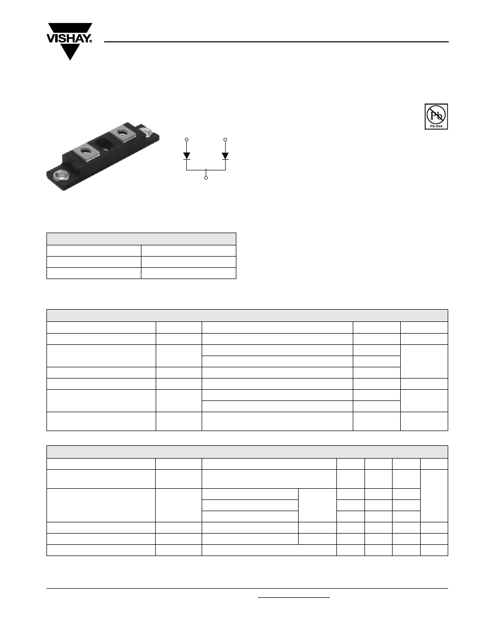
Base common
cathode
Lug
terminal
anode 1
Lug
terminal
anode 2
TO-244
RoHS
COMPLIANT
ABSOLUTE MAXIMUM RATINGS
PARAMETER SYMBOL
TEST
CONDITIONS
MAX.
UNITS
Cathode to anode voltage
V
R
600
V
Continuous forward current
I
F
T
C
= 25 °C
235
A
T
C
= 100 °C
120
Single pulse forward current
I
FSM
Limited by junction temperature
600
Non-repetitive avalanche energy
E
AS
L = 100 µH, duty cycle limited by maximum T
J
2.2
mJ
Maximum power dissipation
P
D
T
C
= 25 °C
463
W
T
C
= 100 °C
185
Operating junction and storage
temperature range
T
J
, T
Stg
- 55 to + 150
°C
ELECTRICAL SPECIFICATIONS PER LEG (T
J
= 25 °C unless otherwise specified)
PARAMETER SYMBOL
TEST
CONDITIONS
MIN.
TYP.
MAX.
UNITS
Cathode to anode
breakdown voltage
V
BR
I
R
= 100 µA
600
-
-
V
Maximum forward voltage
V
FM
I
F
= 105 A
See fig. 1
-
1.38
1.9
I
F
= 210 A
-
1.6
2.25
I
F
= 105 A, T
J
= 125 °C
-
1.3
1.56
Maximum reverse leakage current
I
RM
T
J
= 125 °C, V
R
= 480 V
See fig. 2
-
1.8
6.0
mA
Junction capacitance
C
T
V
R
= 200 V
See fig. 3
-
200
300
pF
Series inductance
L
S
From top of terminal hole to mounting plane
-
6.0
-
nH