St333c..l series, Outline table – C&H Technology ST333C..L SERIES User Manual
Page 6
ST333C..L Series
5
www.irf.com
Bulletin I25187 rev. B 04/00
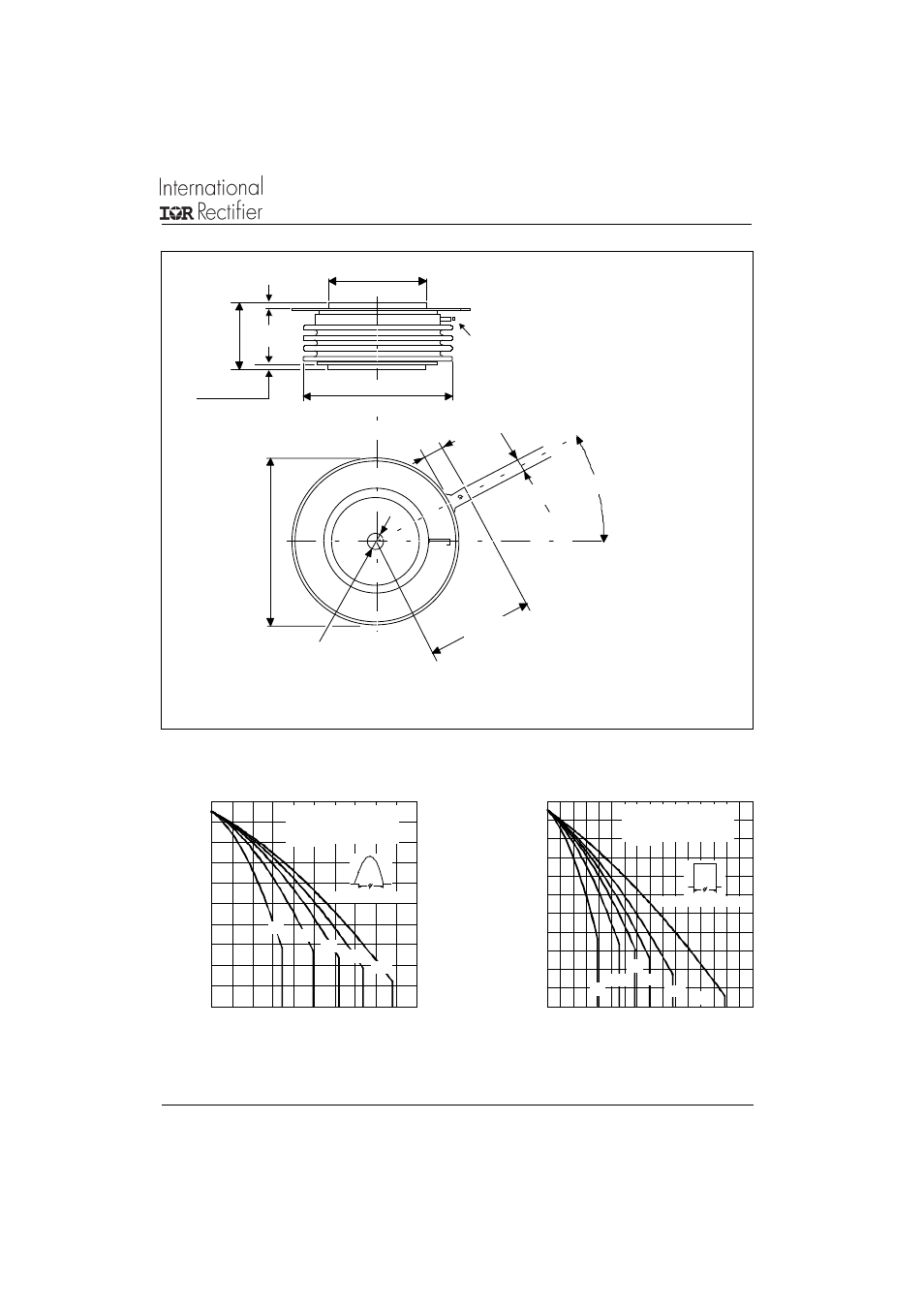
Fig. 1 - Current Ratings Characteristics
Fig. 2 - Current Ratings Characteristics
3 0
4 0
5 0
6 0
7 0
8 0
9 0
10 0
11 0
12 0
13 0
0
1 0 0
2 0 0
30 0
4 0 0
50 0
30°
60 °
9 0°
120 °
1 80°
Average O n-state Current (A)
Co n d uc tio n An g le
M
a
xi
mu
m
A
llo
w
a
bl
e
He
at
si
n
k
T
e
m
p
e
rat
u
re
(
°C
)
ST333C..L Series
(Single Side Cooled )
R (DC) = 0.11 K/W
th J -hs
2 0
3 0
4 0
5 0
6 0
7 0
8 0
9 0
1 0 0
1 1 0
1 2 0
1 3 0
0
1 0 0 2 0 0 3 0 0 4 0 0 5 0 0 6 0 0 7 0 0 8 0 0
D C
3 0 °
6 0 °
9 0 °
1 2 0 °
1 8 0 °
A v e ra g e O n -st a te C u rre n t ( A )
Co nd uc tio n P eriod
M
a
xi
m
u
m
A
llo
w
a
b
le
He
at
si
n
k T
e
m
p
e
rat
u
re
(
°C)
ST 3 3 3 C ..L Se rie s
( Sin g le S id e C o o le d )
R ( D C ) = 0 .1 1 K / W
thJ -h s
Outline Table
TWO PLACES
PIN RECEPTACLE
AMP. 60598-1
0.7 (0.03) MIN.
34 (1.34) DIA. MAX.
53 (2.09) DIA. MAX.
5
8
.5
(
2
.3
) D
IA
. M
A
X
.
2 HOLES DIA. 3.5 (0.14) x
2.5 (0.1) DEEP
4.7 (0.18)
27 (
1
.06)
M
A
X
.
0.7 (0.03) MIN.
6.2 (0.24) MIN.
20°± 5°
36.5 (1.44)
CREPAGE DISTANCE 36.33 (1.430) MIN.
STRIKE DISTANCE 17.43 (0.686) MIN.
Case Style TO-200AC (B-PUK)
All dimensions in millimeters (inches)
Quote between upper and lower
pole pieces has to be considered
after application of Mounting Force
(see Thermal and Mechanical
Specification)