P400 series, Vishay high power products, Passivated assembled circuit elements, 40 a – C&H Technology P400 Series User Manual
Page 4: Triggering, Thermal and mechanical specifications, Circuit type and coding
Document Number: 93755
For technical questions, contact:
www.vishay.com
Revision: 05-Nov-09
3
P400 Series
Passivated Assembled
Circuit Elements, 40 A
Vishay High Power Products
Note
(1)
A mounting compund is recommended and the torque should be checked after a period of 3 hours to allow for the spread of the compound
Note
(1)
To complete code refer to Voltage Ratings table, i.e.: For 600 V P40.W complete code is P402W
TRIGGERING
PARAMETER SYMBOL
TEST
CONDITIONS
VALUES
UNITS
Maximum peak gate power
P
GM
8
W
Maximum average gate power
P
G(AV)
2
Maximum peak gate current
I
GM
2
A
Maximum peak negative gate voltage
-V
GM
10
V
Maximum gate voltage required to trigger
V
GT
T
J
= - 40 °C
Anode supply =
6 V resistive load
3
V
T
J
= 25 °C
2
T
J
= 125 °C
1
Maximum gate current required to trigger
I
GT
T
J
= - 40 °C
90
mA
T
J
= 25 °C
60
T
J
= 125 °C
35
Maximum gate voltage that will not trigger
V
GD
T
J
= 125 °C, rated V
DRM
applied
0.2
V
Maximum gate current that will not trigger
I
GD
2
mA
THERMAL AND MECHANICAL SPECIFICATIONS
PARAMETER SYMBOL
TEST
CONDITIONS
VALUES
UNITS
Maximum junction operating
and storage temperature range
T
J
, T
Stg
- 40 to 125
°C
Maximum thermal resistance,
junction to case per junction
R
thJC
DC operation
1.05
K/W
Maximum thermal resistance,
case to heatsink
R
thCS
Mounting surface, smooth and greased
0.10
Mounting torque, base to heatsink
(1)
4
Nm
Approximate weight
58
g
2.0
oz.
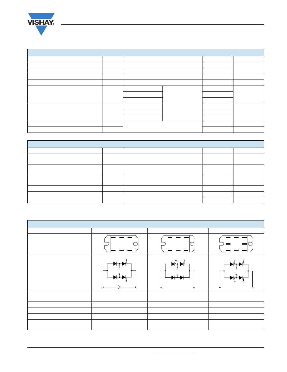
CIRCUIT TYPE AND CODING
(1)
CIRCUIT “0”
CIRCUIT “2”
CIRCUIT “3”
Terminal positions
Schematic diagram
Single phase hybrid bridge
common cathode
Single phase hybrid bridge doubler
Single phase all SCR bridge
Basic series
P40.
P42.
P43.
With voltage suppression
P40.K
P42.K
P43.K
With freewheeling diode
P40.W
-
-
With both voltage suppression
and freewheeling diode
P40.KW
-
-
AC1 G1
-
AC2 G2
+
AC1 G1
-
AC2 G2
+
AC2 G2
-
AC1 G3
G1 G4
+
G1
AC2
AC1
G2
(-)
(+)
G2
G1
AC1
AC2
(-)
(+)
G1
G3
AC2
AC1
(-)
(+)
G2
G4