Vishay high power products – C&H Technology VSK.236..PbF Series User Manual
Page 7
www.vishay.com
For technical questions, contact: [email protected]
Document Number: 94357
6
Revision: 22-Apr-08
VSK.166, .196, .236..PbF Series
Vishay High Power Products
Standard Recovery Diodes, 165 A to 230 A
(New INT-A-PAK Power Modules)
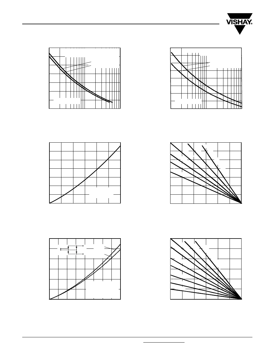
Fig. 14 - Maximum Non-Repetitive Surge Current
Fig. 15 - Maximum Non-Repetitive Surge Current
Fig. 16 - On-State Power Loss Characteristics
Fig. 17 - On-State Power Loss Characteristics
4500
4000
3500
3000
2500
2000
1500
1000
Peal Half Sine Wave
Forward Current (A)
Number of Equal Amplitude Half
Cycle Current Pulses (N)
10
100
1
at 60 Hz 0.0083 s
at 50 Hz 0.0100 s
At any rated load condition and with
rated V
RRM
applied following surge.
VSK.196.. Series
Initial T
J
= 150 °C
5000
4500
4000
3500
3000
2500
2000
1500
1000
Peak Half Sine Wave
Forward Current (A)
Pulse Train Duration (s)
0.1
1.0
0.01
Maximum non-repetitive surge current
Initial T
J
= 150 °C
No voltage reapplied
Rated V
RRM
reapplied
versus pulse train duration.
VSK.196.. Series
0
200
250
300
350
150
100
50
Maximum Total Forward
Power Loss (W)
Total RMS Output Current (A)
50
100
150
200
250
300
0
DC
VSK.196.. Series
Per junction
T
J
= 150 °C
0
300
350
250
200
150
100
50
Maximum Total Forward
Power Loss (W)
Maximum Allowable Ambient
Temperature (°C)
25
50
75
100
125
150
0
R
thSA
= 0
.12 K/
W
-
Δ
R
0.2 K/
W
0.3 K/
W
0.4 K/
W
0.5 K/
W
0.7 K/
W
0
800
600
400
200
1200
1000
Maximum Total Power Loss (W)
Total Output Current (A)
100
200
300
400
0
180°
(Sine)
180°
(Rect)
2 x VSK.196.. Series
Single phase bridge
Connected
T
J
= 150 °C
+
-
~
800
600
400
200
0
1200
1000
Maximum Total Power Loss (W)
Maximum Allowable Ambient
Temperature (°C)
25
125
150
50
75
100
0
0.04 K/
W
0.06 K/
W
0.0
8 K/
W
0.12
K/
W
0.16 K/
W
0.25 K/
W
0.4 K/
W
0.7 K/
W
R
thSA
= 0.02 K/
W
-
Δ
R