Vishay high power products – C&H Technology VSK.236..PbF Series User Manual
Page 6
Document Number: 94357
For technical questions, contact: [email protected]
www.vishay.com
Revision: 22-Apr-08
5
VSK.166, .196, .236..PbF Series
Standard Recovery Diodes, 165 A to 230 A
(New INT-A-PAK Power Modules)
Vishay High Power Products
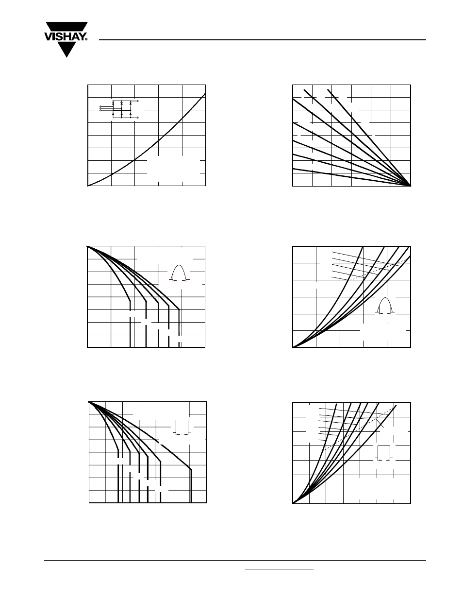
Fig. 9 - On-State Power Loss Characteristics
Fig. 10 - Current Ratings Characteristics
Fig. 11 - Current Ratings Characteristics
Fig. 12 - On-State Power Loss Characteristics
Fig. 13 - On-State Power Loss Characteristics
0
800
600
400
200
1600
1400
1200
1000
Maximum Total Power Loss (W)
Total Output Current (A)
100
200
300
400
500
0
120°
(Rect)
3 x VSK.166.. Series
Three phase bridge
Connected
T
J
= 150 °C
-
~
0
400
200
800
600
1600
1400
1200
1000
Maximum Total Power Loss (W)
Maximum Allowable Ambient
Temperature (°C)
25
50
75
100
125
150
0
0.04 K/
W
0.06 K/
W
0.1 K/
W
0.16 K/
W
0.25 K/
W
0.5 K/
W
R
thSA
= 0.02 K/
W
- Δ
R
70
100
110
120
130
140
150
90
80
Maximum Allowable Case
Temperature (°C)
Average Forward Current (A)
50
100
150
200
250
0
30°
60°
90°
120°
180°
VSK.196.. Series
R
thJC
(DC) = 0.16 K/W
Ø
Conduction angle
70
100
110
120
130
140
150
90
80
Maximum Allowable Case
Temperature (°C)
Average Forward Current (A)
50
100
150
200
250
350
300
0
DC
30°
60°
90°
120°
180°
VSK.196.. Series
R
thJC
(DC) = 0.16 K/W
Ø
Conduction period
0
200
250
300
150
100
50
Maximum Average Forward
Power Loss (W)
Average Forward Current (A)
40
80
120
160
200
0
RMS limit
180°
120°
90°
60°
30°
VSK.196.. Series
T
J
= 150 °C
Conduction angle
Ø
0
300
350
250
200
150
100
50
Maximum Average Forward
Power Loss (W)
Average Forward Current (A)
50
100
150
200
250
300
350
0
DC
180°
120°
90°
60°
30°
RMS limit
VSK.196.. Series
Per junction
T
J
= 150 °C
Ø
Conduction period