Vishay semiconductors – C&H Technology VS-GT300YH120N User Manual
Page 2
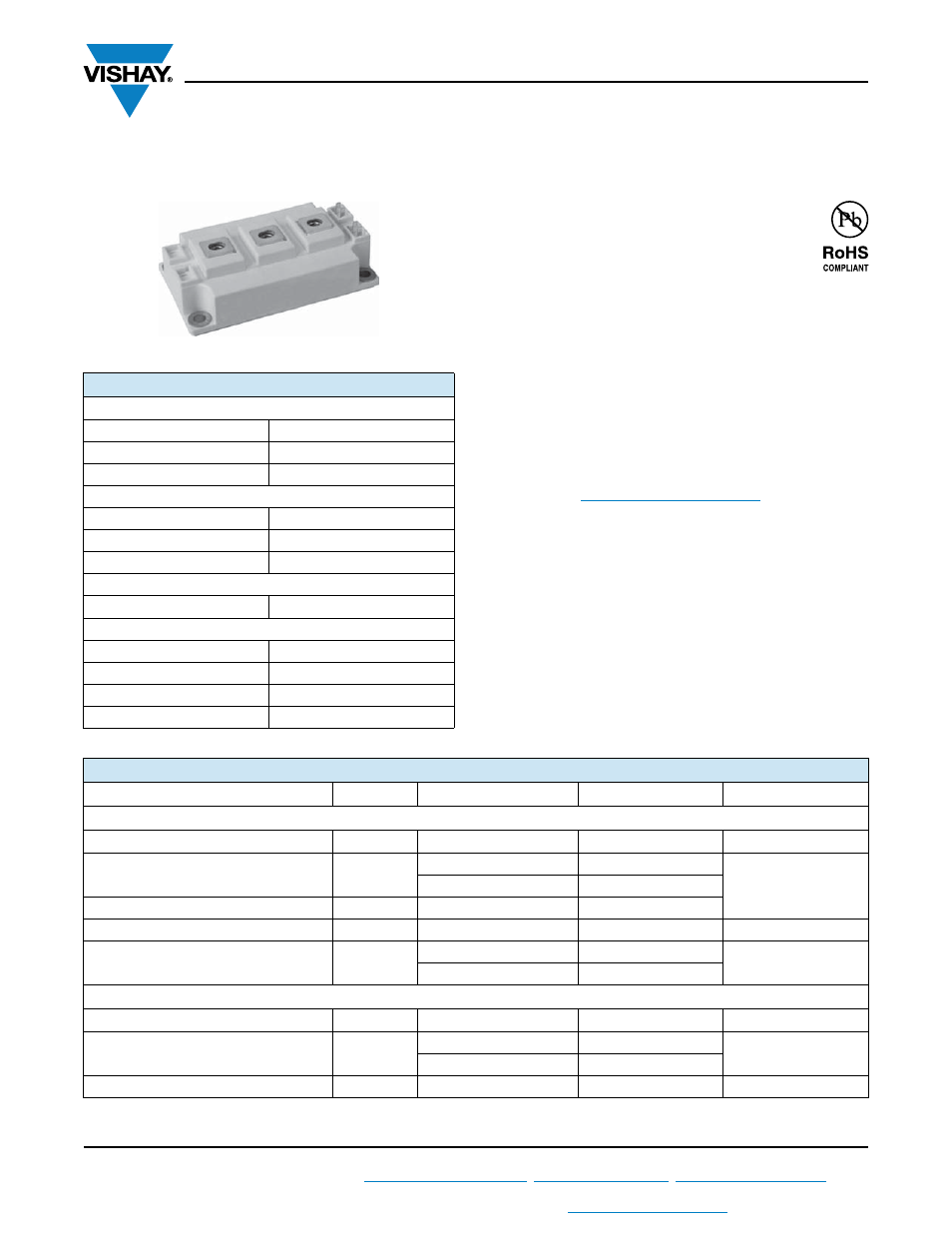
VS-GT300YH120N
www.vishay.com
Vishay Semiconductors
Revision: 25-Jul-13
1
Document Number: 94681
For technical questions within your region:
,
,
THIS DOCUMENT IS SUBJECT TO CHANGE WITHOUT NOTICE. THE PRODUCTS DESCRIBED HEREIN AND THIS DOCUMENT
ARE SUBJECT TO SPECIFIC DISCLAIMERS, SET FORTH AT
www.vishay.com/doc?91000
DIAP Trench IGBT Power Module - 1200 V, 300 A
Current Fed Inverter Topology
FEATURES
• Trench IGBT technology with positive
temperature coefficient
• Low switching losses
• Maximum junction temperature 150 °C
• 10 μs short circuit capability
• Low inductance case
• HEXFRED
®
antiparallel and series diodes with soft reverse
recovery
• Isolated copper baseplate using DCB (Direct Copper
Bonding) technology
• Speed 4 kHz to 30 kHz
• Direct mounting to heatsink
• Material categorization: For definitions of compliance
please see
www.vishay.com/doc?99912
BENEFITS
• Short circuit ruggedness
PRODUCT SUMMARY
IGBT
V
CES
1200 V
V
CE(on)
(typical) at 300 A, 25 °C
2.17 V
I
D(DC)
at T
C
= 48 °C
300 A
HEXFRED
®
SERIES DIODE
V
R
1200 V
V
F
(typical) at 300 A, 25 °C
1.99 V
I
F(DC)
at 49 °C
300 A
IGBT AND HEXFRED
®
SERIES DIODE
V
CE(on)
+ V
F
typical at 300 A
4.12 V
HEXFRED
®
ANTIPARALLEL DIODE
V
F
(typical) at 10 A, 25 °C
1.6 V
I
F(DC)
at 63 °C
40 A
Package
Double INT-A-PAK
Circuit
Current Fed Inverter Topology
Double INT-A-PAK
ABSOLUTE MAXIMUM RATINGS (T
C
= 25 °C unless otherwise noted)
PARAMETER
SYMBOL
TEST CONDITIONS
MAX.
UNITS
IGBT
Collector to emitter voltage
V
CES
1200
V
Collector current
I
C
T
C
= 80 °C
234
A
T
C
= 25 °C
341
Clamped inductive load current
I
LM
700
Gate to emitter voltage
V
GE
± 30
V
Maximum power dissipation
P
D
T
C
= 80 °C
583
W
T
C
= 25 °C
1042
SERIES DIODE
Cathode to anode breakdown voltage
V
RRM
1200
Continuous forward current
I
F
T
C
= 80 °C
232
A
T
C
= 25 °C
348
Peak repetitive forward current
I
FSM
T
C
= 25 °C
2200
A