Ld41, Pow-r-blok, Junction to case) – C&H Technology LD41__60 User Manual
Page 5: Tj = 150 °c ), Conduction angle, Sinusoidal waveform), Rectangular waveform)
Powerex, Inc., 173 Pavilion Lane, Youngwood, Pennsylvania 15697 (724) 925-7272
POW-R-BLOK
TM
http://www.pwrx.com
Dual Diode Isolated Module
600 Amperes / Up to 2600 Volts
Revision Date: 01/14/2010
LD41__60
0
0.01
0.02
0.03
0.04
0.05
0.06
0.07
0.001
0.01
0.1
1
10
100
Ther
m
al
Im
pedance
-Z
jc
-
°C
/W
Time - t - Seconds
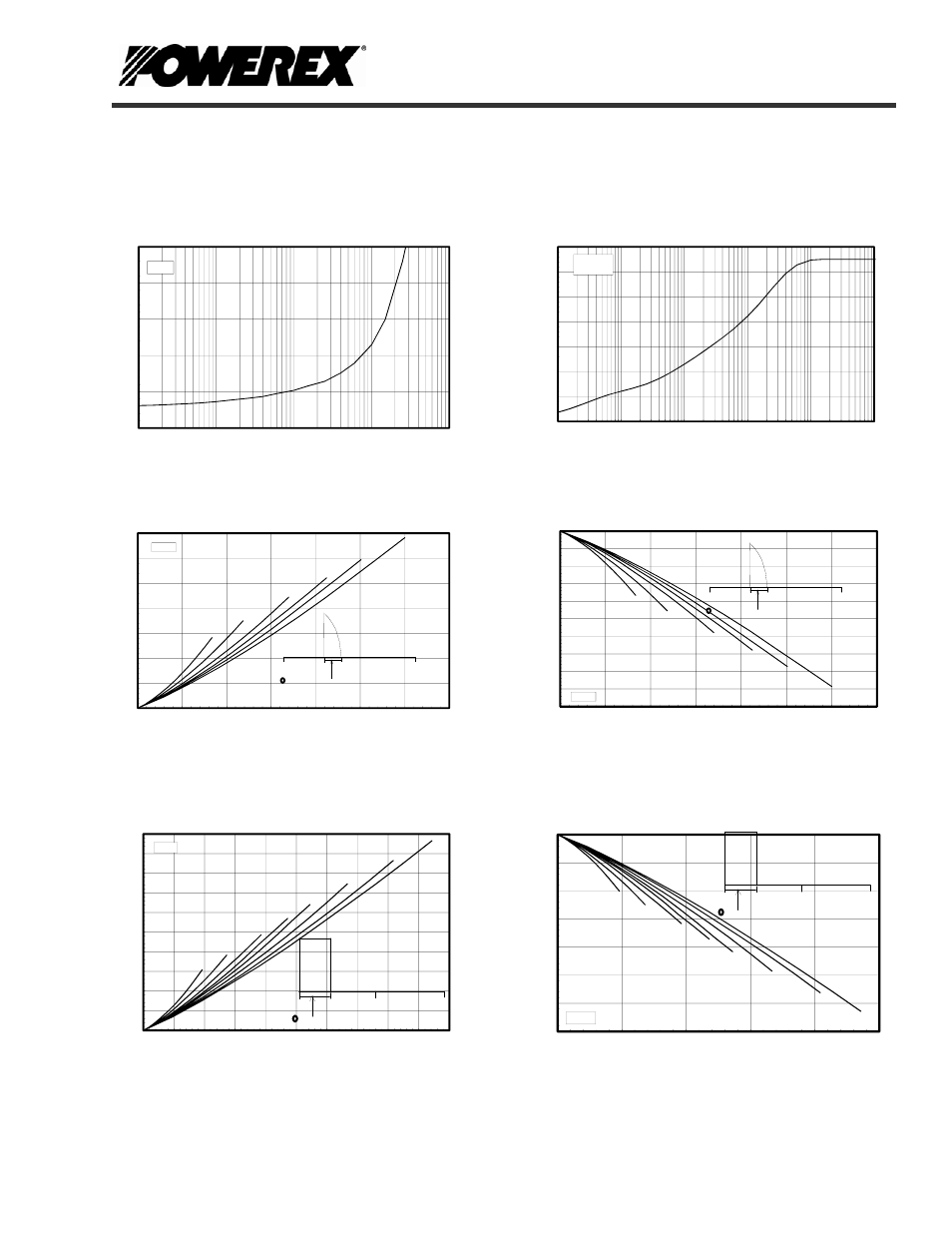
Maximum Transient Thermal Impedance
(Junction to Case)
0.00
1.00
2.00
3.00
4.00
5.00
10
100
1000
10000
100000
On-State Voltage
-
Vfm
-
Volts
Instantaneous On-State Current - Ifm - Amperes
Maximum On-State Forward Voltage Drop
( Tj = 150 °C )
0
180
360
CONDUCTION ANGLE
15°
30°
60°
90°
120°
180°
0
100
200
300
400
500
600
700
0 100 200 300 400 500 600 700
Max.
P
ower
D
issi
pati
on
Per D
iode
-W
atts
Average On-State Current - If(av) - Amperes
Maximum On-State Power Dissipation
(Sinusoidal Waveform)
0
180
360
CONDUCTION ANGLE
15°
30°
60°
90°
120°
180°
100
105
110
115
120
125
130
135
140
145
150
0 100 200 300 400 500 600 700
Max.
Case
Te
mp
eratu
re -
Tcase
-°C
Average On-State Current - If(av) - Amperes
Maximum Allowable Case Temperature
(Sinusoidal Waveform)
0
180
360
CONDUCTION ANGLE
15°
30°
60°
90°
120°
180°
270°
360°
0
100
200
300
400
500
600
700
800
900
1000
0 100 200 300 400 500 600 700 800 900 1000
M
ax.
Pow
er Dissipation
Per Diode
-W
atts
Average On-State Current - If(av) - Amperes
Maximum On-State Power Dissipation
(Rectangular Waveform)
0
180
360
CONDUCTION ANGLE
15°
30°
60°
90°
120°
180°
270°
360°
80
90
100
110
120
130
140
150
0 200 400 600 800 1000
Max. C
ase Temper
atur
e
-T
case
-°C
Average On-State Current - If(av) - Amperes
Maximum Allowable Case Temperature
(Rectangular Waveform)