Cpv364m4kpbf, Vishay high power products – C&H Technology CPV364M4KPbF User Manual
Page 5
www.vishay.com
For technical questions, contact: [email protected]
Document Number: 94488
4
Revision: 01-Sep-08
CPV364M4KPbF
Vishay High Power Products
IGBT SIP Module
(Short Circuit Rated
Ultrafast IGBT)
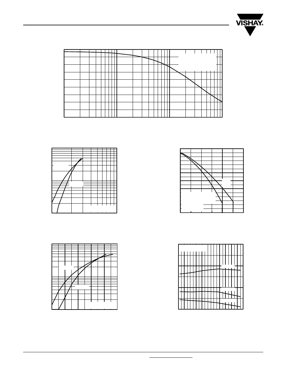
Fig. 1 - Typical Load Current vs. Frequency
(Load Current = I
RMS
of Fundamental)
Fig. 2 - Typical Output Characteristics
Fig. 3 - Typical Output Characteristics
Fig. 4 - Maximum Collector Current vs.
Case Temperature
Fig. 5 - Typical Collector to Emitter Voltage vs.
Junction Temperature
0.1
1
10
100
0
2
4
6
8
10
12
14
16
18
f, Frequency (KHz)
L
O
AD CURRENT
(A)
Tc = 90°C
Tj = 125°C
Power Factor = 0.8
Modulation Depth = 1.15
Vcc = 50% of Rated Voltage
0.00
0.59
1.17
1.76
Total Output Power (kW)
3.51
5.27
2.34
2.93
4.10
4.68
1
10
100
1
10
V , Collector-to-Emitter Voltage (V)
I , C
o
lle
c
to
r-to
-E
m
itte
r C
u
rre
n
t (A
)
CE
C
V = 15V
20µs PULSE WIDTH
GE
T = 25 C
J
°
T = 150 C
J
°
1
10
100
5
6
7
8
9
10
V , Gate-to-Emitter Voltage (V)
I , C
o
lle
c
to
r-to
-E
m
itte
r C
u
rre
n
t (A
)
GE
C
V = 50V
5µs PULSE WIDTH
CC
T = 25 C
J
°
T = 150 C
J
°
0
5
10
15
20
25
30
0
20
40
60
80
100
120
140
160
DC
Square wave (D=0.50)
80% rated Vr applied
see note (2)
T
C
, Case Temperature (°C)
Maximum DC Collector Current (A)
-60 -40 -20
0
20
40
60
80 100 120 140 160
1.0
2.0
3.0
4.0
T , Junction Temperature ( C)
V
, C
o
lle
c
to
r-to
-E
m
itte
r V
o
lta
g
e
(V
)
J
°
CE
V = 15V
80 us PULSE WIDTH
GE
I = A
26
C
I = A
13
C
I = A
6.5
C