Vsk.l240 series, Vishay high power products, Fast recovery diodes, 250 a (magn-a-pak – C&H Technology VSK.L240 Series User Manual
Page 4: Power modules)
Document Number: 93164
For technical questions, contact: [email protected]
www.vishay.com
Revision: 22-Apr-08
3
VSK.L240 Series
Fast Recovery Diodes, 250 A
(MAGN-A-PAK
TM
Power Modules)
Vishay High Power Products
Note
• The table above shows the increment of thermal resistance R
thJC
when devices operate at different conduction angles than DC
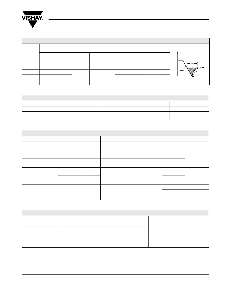
RECOVERY CHARACTERISTICS
CODE
MAXIMUM VALUE
AT T
J
= 25 °C
TEST CONDITIONS
TYPICAL VALUES
AT T
J
= 150 °C
t
rr
AT 25 % I
RRM
(µs)
I
pk
SQUARE
PULSE
(A)
dI/dt
(A/µs)
V
r
(V)
t
rr
AT 25 % I
RRM
(µs)
Q
rr
(µC)
I
r
(A)
S10
1.0
500
100
- 50
2.7
135
100
S20
2.0
3.5
250
145
S30
3.0
3.6
360
200
BLOCKING
PARAMETER
SYMBOL
TEST CONDITIONS
VALUES
UNITS
Maximum peak reverse leakage current
I
RRM
T
J
= 150 °C, leakage current
50
mA
RMS insulation voltage
V
INS
50 Hz, circuit to base, all terminals shorted, 25 °C,
t = 1 s
3000
V
I
FM
t
rr
di
dt
I
RM(REC)
Q
rr
t
THERMAL AND MECHANICAL SPECIFICATIONS
PARAMETER
SYMBOL
TEST CONDITIONS
VALUES
UNITS
Maximum junction operating and
storage temperature range
T
J
, T
Stg
- 40 to 150
°C
Maximum internal thermal resistance,
junction to case per junction
R
thJC
DC operation
0.125
K/W
Thermal resistance,
case to heatsink per module
R
thCS
Mounting surface flat, smooth and greased
0.02
Mounting torque ± 10 %
MAP to heatsink
A mounting compound is recommended and
the torque should be rechecked after a
period of about 3 hours to allow for the
spread of the compound.
4 to 6
Nm
busbar to MAP
8 to 10
Approximate weight
850
g
30
oz.
Case style
MAGN-A-PAK
ΔR CONDUCTION PER JUNCTION
CONDUCTION ANGLE
SINUSOIDAL CONDUCTION RECTANGULAR CONDUCTION
TEST CONDITIONS
UNITS
180°
0.008
0.007
T
J
= T
J
maximum
K/W
120°
0.010
0.011
90°
0.013
0.015
60°
0.019
0.020
30°
0.032
0.033