19 zener barriers - operating instructions, Application examples, Hazardous area safe area – VEGA Z728 Zener barriers User Manual
Page 19: Harzardous area safe area
19
Zener barriers - operating instructions
Application examples
Subject to reasonable modifications due to technical advances.
Copyright Pepperl+Fuchs, Printed in Germany
Pepperl+Fuchs Group • Tel.: Germany +49 621 776-0 • USA +1 330 4253555 • Singapore +65 67799091 • Internet http://www.pepperl-fuchs.com
Da
te of issu
e
05/2
3
/03
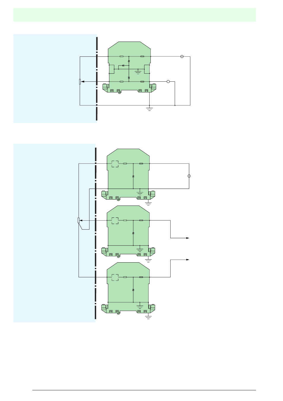
Potentiometric position detection
Applications in which the accuracy is not critical can be
satisfied as shown above. The intrinsically safe circuit has a
direct connection to ground. An additional resistance on this
side would have an effect on the voltage signal and would have
to be taken into account. The system is approved for [EEx ia]
IIC.
If greater accuracy is required, a 4-wire solution must be
applied. The Z715 Zener barrier transfers the power supply to
the potentiometer, whilst two Z715.1K barriers transfer the
signal to the receiver. The supply voltage in the example above
could be 13 V.
Hazardous area
Safe area
V
Z960
x3
x3
x3
1
2
3
4
8
7
6
5
Harzardous area
Safe area
Signal
Z715
x3
CL
1
2
8
7
Z715.1K
x3
CL
1
2
8
7
Z715.1K
x3
CL
1
2
8
7