13 zener barriers - operating instructions, Application examples, Hazardous area safe area – VEGA Z728 Zener barriers User Manual
Page 13
13
Zener barriers - operating instructions
Application examples
Subject to reasonable modifications due to technical advances.
Copyright Pepperl+Fuchs, Printed in Germany
Pepperl+Fuchs Group • Tel.: Germany +49 621 776-0 • USA +1 330 4253555 • Singapore +65 67799091 • Internet http://www.pepperl-fuchs.com
Da
te of issu
e
05/2
3
/03
1.7
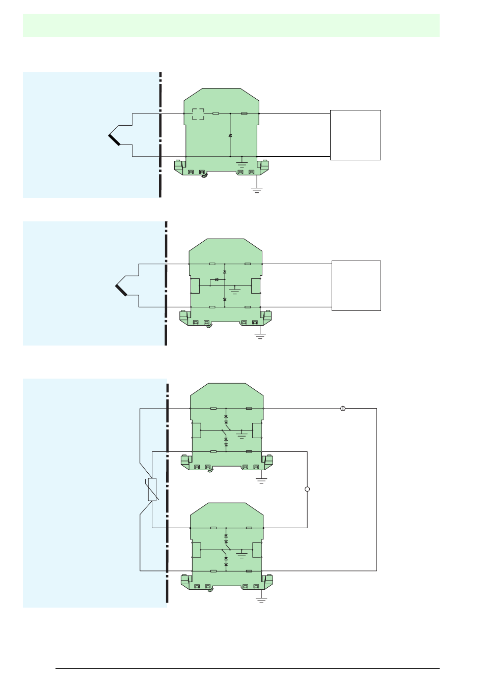
Application examples
Temperature measurement
The simplest and most favourably priced solution is a single-
channel Zener barrier. It should be noted, however, that the
device is not grounded in the safe area. The system is
approved for [EEx ia] IIC.
The use of a two-channel barrier prevents the direct ground
connection of the intrinsically safe circuit. Grounding only takes
place in the event of a fault, when the Zener diodes conduct.
This circuit arrangement prevents the occurrence of mutual
interference between the various circuits. The system is
approved for [EEx ia] IIC.
The illustration shows the set up for a temperature
measurement with a 4-wire Pt100. None of the 4 wires is
connected directly to ground. The complete system is therefore
"quasi ground-free".
This is the best option when the intention is to suppress the
influence of the end-to-end resistance of the barrier on the
measuring accuracy as far as possible.
Temperature
monitoring
or control
Hazardous area
Safe area
Not grounded
Z705
x3
CL
1
2
8
7
Temperature
monitoring
or control
Hazardous area
Safe area
Z960
x3
x3
x3
1
2
3
4
8
7
6
5
Hazardous area
Safe area
V
Z961
x3
x3
x3
x3
1
2
3
4
8
7
6
5
Z961
x3
x3
x3
x3
1
2
3
4
8
7
6
5