12 zener barriers - operating instructions, How to select the correct barrier – VEGA Z728 Zener barriers User Manual
Page 12
12
Zener barriers - operating instructions
How to select the correct barrier
Subject to reasonable modifications due to technical advances.
Copyright Pepperl+Fuchs, Printed in Germany
Pepperl+Fuchs Group • Tel.: Germany +49 621 776-0 • USA +1 330 4253555 • Singapore +65 67799091 • Internet http://www.pepperl-fuchs.com
Da
te of issu
e
05/2
3
/03
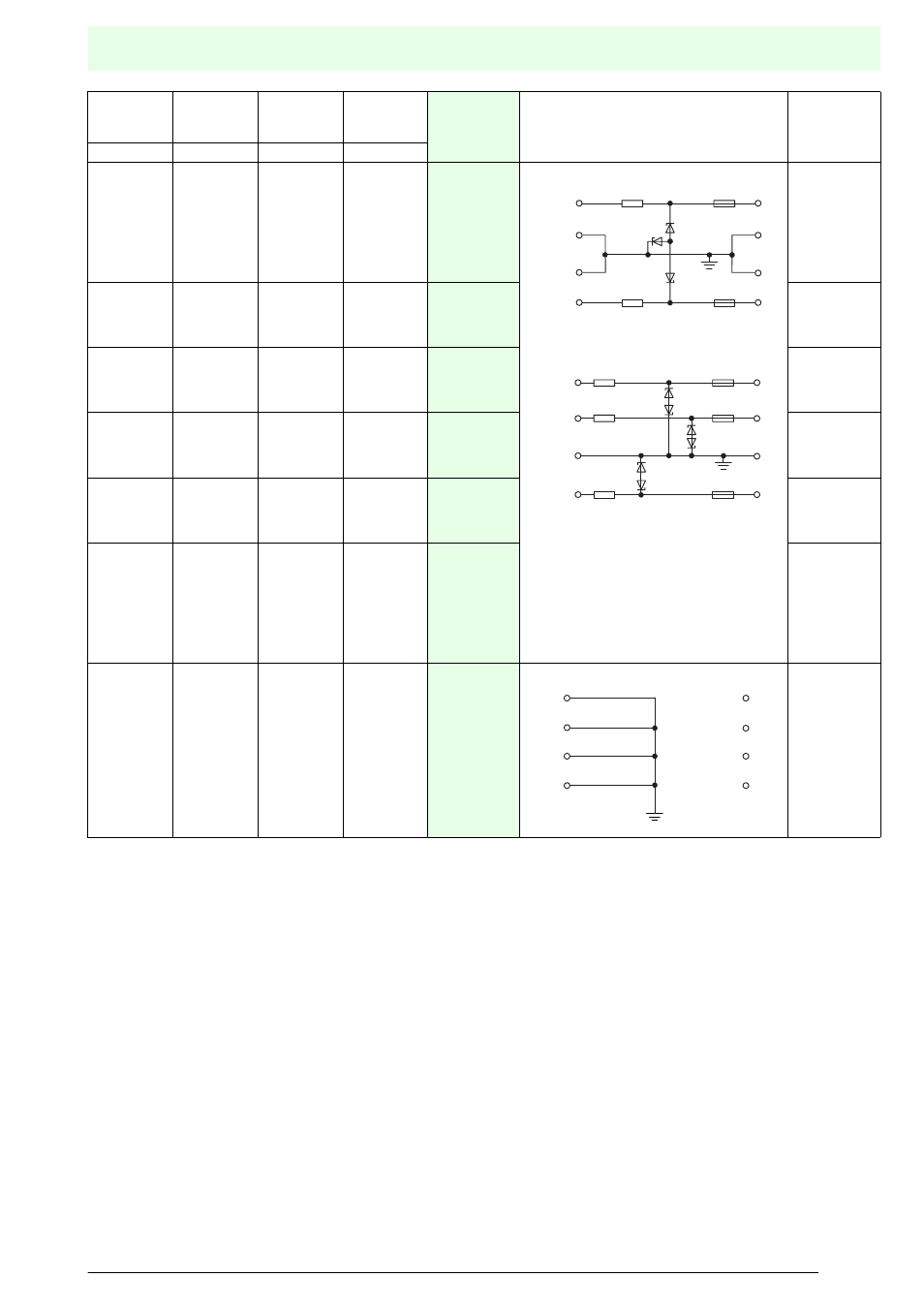
Note 1:
Zener barriers type Z787H and Z887H have channels with
diode returns.
The Ex-terminals for the channels with diode returns should be
regarded as 28 V voltage sources.
The 28 V must be considered as the theoretical maximum up
to which a capacitive load can be applied to the Ex-terminals
due to the leakage current of the diode return. This voltage is
only used in calculating the load capacitance.
Note 2:
A1, A2 and A3 are separate channels.
B: Two channels in parallel circuit with a ground connection.
C: Two channels in series circuit without a ground return.
Max.
end-to-end
resistance
U
in
at 10 µA
U
in
max
Fuse rating
see circuit
diagram No.
Circuit diagram
Hazardous area
Safe area
connections
connections
see note 2
W
V
V
mA
64
64
–
–
75
75
6.5
6.5
–
–
6.5
6.5
9.5
9.5
–
–
9.7
9.7
50
50
–
–
50
50
10)
10)
11)
A1
A2
B
A1
A2
B
115
115
–
13.0
13.0
–
14.2
14.2
–
50
50
–
10)
A1
A2
B
136
136
–
15.0
15.0
–
16.2
16.2
–
50
50
–
10)
A1
A2
B
327
327
–
19.0
19.0
–
20.9
20.9
–
50
50
–
10)
A1
A2
B
646
646
–
26.0
26.0
–
27.6
27.6
–
50
50
–
10)
A1
A2
B
27.27
27.27
27.27
–
–
–
0.9 (1 µA)
0.9 (1 µA)
0.9 (1 µA)
–
–
–
4.9
4.9
4.9
–
–
–
50
50
50
–
–
–
11)
A1
A2
A3
B
B
C
1
8
4
5
2
7
3
6
x3
x3
1
8
4
5
3
6
2
7
x3
x3
x3
1
8
4
5
2
7
3
6