VEGA VEGAFLEX 81 4 … 20 mA_HART two-wire User Manual
Page 83
83
11 Supplement
VEGAFLEX 81 • 4 … 20 mA/HART two-wire
41824-EN-130612
Ʋ Min. distance to installations
> 500 mm (19.69 in)
Ʋ Vessel
metallic, ø 1 m (3.281 ft), centric installation, process
fitting flush with the vessel ceiling
Ʋ Medium
Water/Oil (dielectric constant ~2.0)
4)
Ʋ Installation
Probe end does not touch the vessel bottom
Sensor parameter adjustment
No gating out of false signals carried out
Typical deviation - Interface measure-
ment
± 5 mm (0.197 in)
Typical deviation - Total level interface
measurement
See following diagrams
Typical deviation - Level measurement
5)6)
See following diagrams
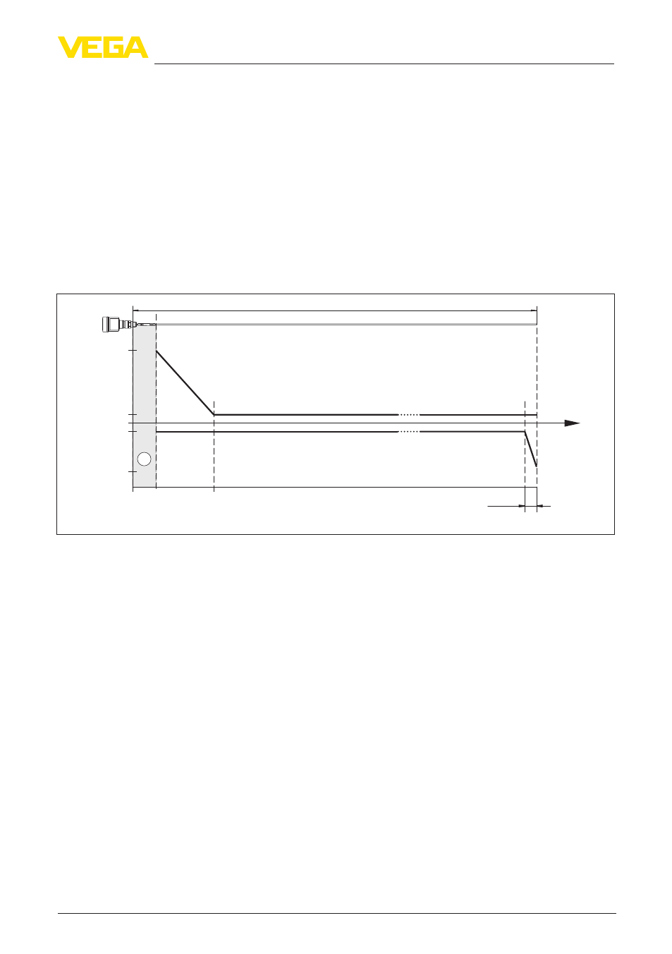
L
0
-2 mm
(-0.079
")
2 mm
(0.079
")
15 mm
(0.591
"
)
-10 mm
(-0.394
")
0,3 m
(11.811
"
)
0,08 m
(3.15
"
)
0,02 m
(0.787
")
1
Fig. 48: Deviation VEGAFLEX 81 in rod version in water
1 Dead band - no measurement possible in this area
L Probe length
4)
With interface measurement = 2.0
5)
Depending on the installation conditions, there can be deviations which can be rectified with an adaptation of
the adjustment or a change of the measured value offset in the DTM service mode
6)
The dead bands can be optimizes by a false signal suppression.