4 mounting, 1 general instructions, 2 instructions for installation – VEGA VEGAPULS 66 (≥ 2.0.0 - ≥ 4.0.0) enamel Modbus and Levelmaster protocol User Manual
Page 14
14
4 Mounting
VEGAPULS 66 enamel • Modbus and Levelmaster protocol
41368-EN-121011
4 Mounting
4.1 General instructions
With instruments with threaded process fitting, suitable tools must be
applied for tightening the hexagon.
Warning:
The housing must not be used to screw the instrument in! Applying
tightening force can damage internal parts of the housing.
Use the recommended cables (see chapter "Connecting to power
supply") and tighten the cable gland.
You can give your instrument additional protection against moisture
penetration by leading the connection cable downward in front of the
cable entry. Rain and condensation water can thus drain off. This ap-
plies mainly to outdoor mounting as well as installation in areas where
high humidity is expected (e.g. through cleaning processes) or on
cooled or heated vessels.
Make sure that all parts of the instrument exposed to the process, in
particular the active measuring component, process seal and process
fitting, are suitable for the existing process conditions. These include
above all the process pressure, process temperature as well as the
chemical properties of the medium.
You can find the specifications in chapter "Technical data" and on the
type label.
4.2 Instructions for installation
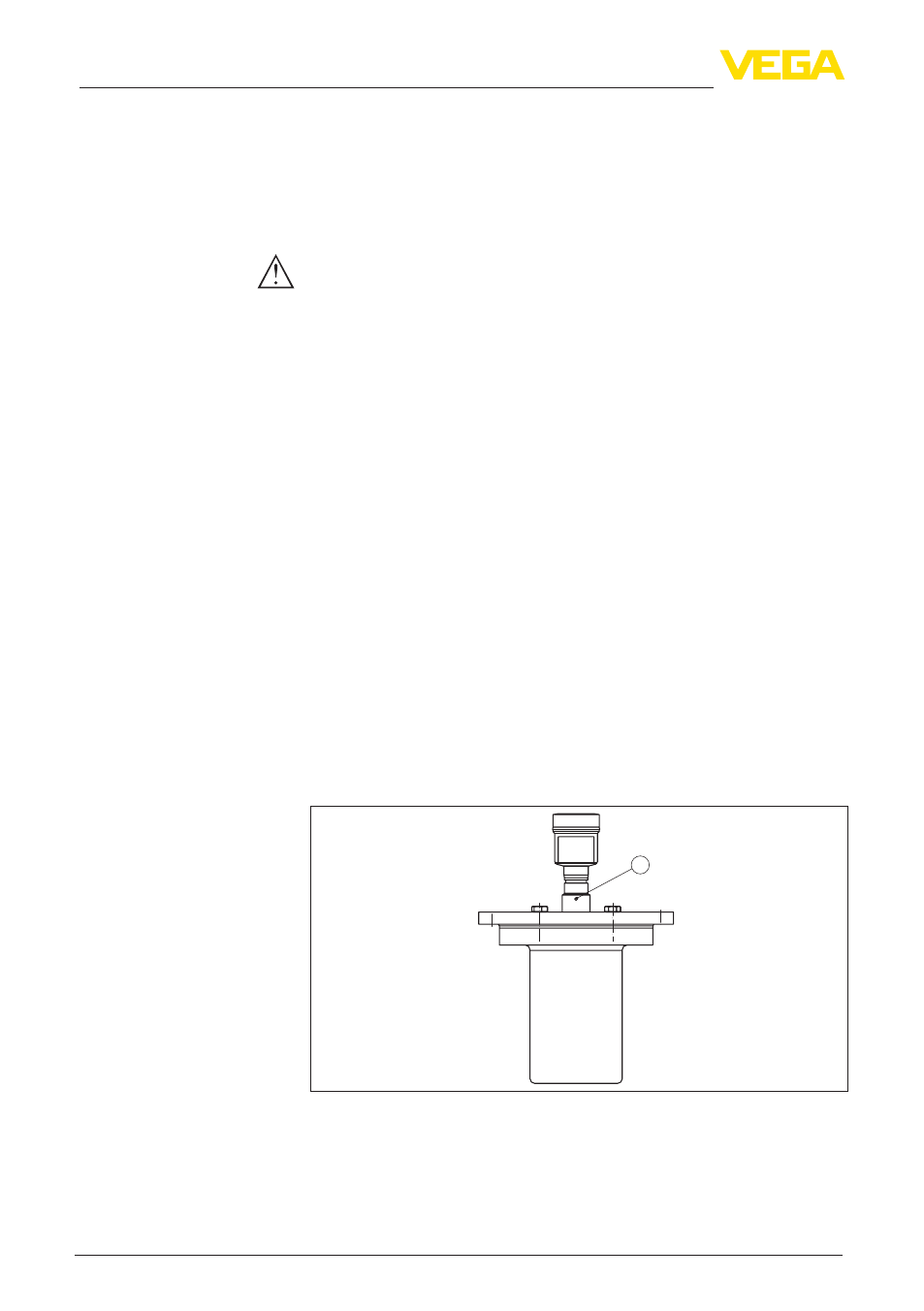
The emitted radar impulses of VEGAPULS 66 are electromagnetic
waves. The polarisation plane is the direction of the electrical share.
Their position is marked on the instrument.
1
Fig. 6: Position of the polarisation level
1 Marking hole
When mounting the VEGAPULS 66, keep a distance of at least
500 mm (19.69 in) to the vessel wall. If the sensor is installed in the
Screwing in
Moisture
Suitability for the process
conditions
Polarisation plane
Installation position